- Joined
- Sep 12, 2010
- Messages
- 3,131
- Reaction score
- 415
- Points
- 123
- Location
- Rome
- Website
- www.tuttovola.org
Will the MicroTextures be added to the D3D9client zip at some point, or will it remain a separate download?
ORBITER-FORUM will be temporarily closed at 2026-07-23 18:00 UTC while we complete some OF maintenance tasks. The amount of downtime is expected to take up to one hour, but probably less.
I hope this is jedidia after installing [email protected] lol


I wonder if it would be worth high-pass filtering the microtexture (offline, not on the fly by the client!).


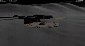
It's too dark yet, but I'm in a hurry today. A final release V1.3 will be published tomorrow.
No, it indeed doesn't sound right. I thought at first I've done a buzz job, but ...This doesn't sound right. The microtextures shouldn't have any noticeable effect on the overall surface albedo. This goes in particular for the high-pass filtered textures, which shouldn't contain any low-frequency content anymore (which carries the mean brightness information).
Maybe there is a mismatch between the convention you used to prepare the microtexture, and the way jarmonik blends the microtexture with the underlying global texture.
One sensible convention might be this: an RGB value of 0.5 in the microtexture represents the neutral intensity level. Any lower values darkens the blend result, any higher values brighten it.

Dear Marg, this is a known issue for those textures based on Apollo / ALSJ image sources, but as a previous discussion and attempt in this thread has shown, it is not a prudent solution to try and make a normal map out of this material. This is why as parallel evolution of the microtextures ( => version 2.x) I am about to create an artifical set via Povray - with this, we can have true normal maps to realize your very welcome suggestions. I need to dig into my archives for Povray code I have used years ago to achieve a very basic crater-filled landscape ... I need some time to make this code generate fully realistic images ... in the meantime l try to freeze a stable V1.x texture set with the known limitations you've correctly noted (at least it makes folks like jedidia happyTexture patterns themselves are good (B- classic lunar mid-range view), but shouldn't they be in that original format (RGB channels etc.) because there is some odd effect when changing direction of view (when angle to the sun changes). In previous format it looked (I think all this "normal map" thing) more realistic.
") ).
).at least it makes folks like jededia happy
No, it indeed doesn't sound right. I thought at first I've done a buzz job, but ...
- mean value is close to 0.5:
The blend equations is simply:
float3 cFnl = (cFar+0.5f) * (cMed+0.5f) * (cLow+0.5f);
So, the albedo from each texture is offset upwards by 0.5f resulting that each texture will range from 0.5f to 1.5f and then the results are multiplied.
If all channels of every texture is filled with 128 then the equation will become
1 * 1 * 1 = 1
Meaning that no change will occur to the color from a tile textures.
I noticed that some of the lowest mipmaps in _A texture were shifted about 7-10% towards dark. Fixing that cured the problem here. I'll take a look if we can do color balance corrections on a client side.
- I.e.: is (A) the tile size fixed, and an increased texture size just adds more crisp details to the tile, or does (B) the shader automatically increase the tile area size with a bigger texture size ?
These three lines in Surface.fx- If it is case(A), then: where is the tile size defined, and are there different sizes for _A, _B, and _C levels ?
float3 cFar = tex2D(MicroCS, UVn*8.0f).rgb;            // High altitude micro texture C
float3 cMed = tex2D(MicroBS, UVn*64.0f).rgb;        // Medimum altitude micro texture B
float3 cLow = tex2D(MicroAS, UVr*512.0f).rgb; // Low altitude micro texture A- Are there currently fixed limits to the texture size, e.g. 2048x2048, or would 4096x4096 work as well without further modifications ?
- And how does the tile size map to the rendered area (physical dimensions) ?
Do cFar, cMed and cLow refer to three levels of microtexture, or does one of these refer to the global surface texture?
It refers to three different levels of micro textures. The final step is:
// Apply luminance
cTex.rgb *= lerp(1.0f, cFnl.b, step1);
where "step1" is a sort of smooth on/off switch. So, depending the value of "step1" the eqation becomes.
cTex.rgb *= 1.0f or
cTex.rgb *= cFnl.b;
float4 SurfaceTechPS(TileVS frg) : COLOR
{
	float3 cNgt = 0;
	float3 cSpe = 0;
	float4 cTex = tex2D(DiffTexS, frg.texUV.xy);
	float4 cMsk = tex2D(MaskTexS, frg.texUV.xy);

	float3 nrmW = frg.nrmW;					// Per-vertex surface normal vector
	float3 nvrW = frg.nrmW;					// Per-vertex surface normal vector
	float3 camW = normalize(frg.camW);		// Unit viewing ray
	float3 vVrt = vCameraPos - frg.camW;	// Geo-centric vertex position
	float3 vPlN = normalize(vVrt);			// Planet mean normal
	float  fRad = dot(vVrt, vPlN);			// Pixel Geo-distance

	// Specular Water reflection
	//
	if (bSpecular) {

		#if defined(_SURFACERIPPLES)
			float Fct = min(2.0f, 10000.0f / fCameraAlt);
			float3 cNrm = (tex2D(OceaTexS, frg.texUV.zw).xyz - 0.5f) * Fct;
			cNrm.z = cos(cNrm.x * cNrm.y * 1.570796);
			// Compute world space normal
			nrmW = (vTangent * cNrm.r) + (vBiTangent * cNrm.g) + (vPlN * cNrm.b);
		#endif

		float f = 1.0-saturate(dot(camW, nrmW));
		float s = dot(reflect(-vSunDir, nrmW), camW);
		float m = (1.0 - cMsk.a) * saturate(0.5f-frg.aux[AUX_NIGHT]*2.0f);

		cSpe = m * pow(saturate(s), 200.0f) * vWater.rgb * 2.0f;

		float3 cSky = float3(1.2, 1.4, 3.5) * 0.7;
		cTex.rgb = lerp(cTex.rgb, cSky, m * (f*f*f*f));
	}

	else {

		if (bMicro) {

			float dist = frg.aux[AUX_DIST];

			float2 UV  = frg.texUV.xy;

			float3 cFar = tex2D(MicroCS, UV*8.0f).rgb;			// High altitude micro texture C
			float3 cMed = tex2D(MicroBS, UV*64.0f).rgb;			// Medimum altitude micro texture B
			float3 cLow = tex2D(MicroAS, UV*512.0f).rgb;		// Low altitude micro texture A

			float step1 = smoothstep(25000, 12000, dist);

			float3 cFnl = (cFar+0.5f) * (cMed+0.5f) * (cLow+0.5f);

			// Create normals
			float3 cNrm  = float3((cFnl.xy - 1.0f) * 2.0f, 0) * step1;
			cNrm.z = cos(cNrm.x * cNrm.y * 1.57);

			// Approximate world space normal
			//nrmW = normalize(-(vTangent * cNrm.x) + (vBiTangent * cNrm.y) + (nrmW * cNrm.z));

			// Apply luminance
			cTex.rgb *= lerp(1.0f, cFnl.b, step1);
		}
	}

	// Do we have an atmosphere ?
	//
	if (!bOnOff) { // No

		float fDRP = dot(vPlN, vSunDir);

		nrmW = lerp(nrmW, vPlN, pow(0.05, saturate(fDRP)));

		float fDNS = dot(nrmW, vSunDir);
		float fDNR = dot(nrmW, camW);
		float fDRS = dot(camW, vSunDir);

		float fX = saturate(fDNS);						// Lambertian
		float fY = 0.05 + saturate(fDNR)*0.4;			// Lommel-Seeliger compensation
		float fZ = pow(abs(fDRS),10.0f) * 0.3f;			// Shadow compensation
		float fLvl = fX * (fZ+rcp(fX+fY)) * fExposure;	// Bake all together

		float3 color = cTex.rgb * max(fLvl, 0);			// Apply sunlight

		return float4(pow(abs(color), fAux4), 1.0f);	// Gamma corrention
	}

	else { // Yes, atmosphere is present

		if (bLights) frg.atten.rgb += 3.0f * cMsk.rgb * (saturate(frg.aux[AUX_NIGHT]) * fNight);
		float3 color = cTex.rgb * frg.atten.rgb + cSpe + frg.insca.rgb + cNgt;
		color = (1.0f - exp2(-color*fExposure)) * vWhiteBalance;
		return float4(pow(abs(color), fAux4), 1.0f);
	}
}What do you think about this alternative instead?
cFnl = 2/3 * (cFar + cMed + cLow)
What do you think about this alternative instead?
cFnl = 2/3 * (cFar + cMed + cLow)
What do you think about this alternative instead?
cFnl = 2/3 * (cFar + cMed + cLow)
Actually, this probably means that my second suggestion will turn out much too dark.