SSU Crawler Transporter development

CT is complete! Attached the completion screenshots to this thread.
 

Attachments

  • CT_complete_1.jpg
    CT_complete_1.jpg
    84.9 KB · Views: 728
  • CT_complete_2.jpg
    CT_complete_2.jpg
    89.9 KB · Views: 804
  • CT_complete_3.jpg
    CT_complete_3.jpg
    88.4 KB · Views: 953
OK, what now? ;)
 
OK, what now? ;)
Now it's up to you coders to implement it. My suggestion is posted above. Just need Donamy to complete the cab interior.
 
Below is a first trial of the CT meshes in Orbiter using Tschachim's fine work. The only thing that needs to be added/modified is this:

-Readjustment of the VC elements
-Exhaust duct exhausts
-Make it capable of handling the SSU elements, instead of the Project Apollo elements. Currently it is operating through a "cheat" of some sorts that allows it to be decoupled from it's dependance on Project Apollo elements.
-Implementation of a JEL hydraulic system.
 

Attachments

  • CT1_parksite.jpg
    CT1_parksite.jpg
    310.6 KB · Views: 903
Meshes and textures have been checked in.
 
Anyone willing to implement this? Especially with the second rollout of the STS-125 flow coming up and the second rollout for the STS-400 flow(April 17).
 
Last edited:
To close-out development on the SSU CT here's a list of the work needed:


  • Correct modelling of the Crawler physical behaviour in regards to motors/generators
  • Driver cab panels, I'm working on them, plan to complete them once the new RSS is done
  • Exhaust coming out of the six exhaust nozzles
  • A comm mode for talking with the Engineering Room and outside observers
  • Fixing various mesh-related bugs such as the height of the CT and making sure that the drive-truck struts doesn't get disconnected from the main-body as they curretly get when you jack up the CT
  • And finally: How-to documentation on the CT, how to activate it, driving it, how to secure it, how to operate the Laser Docking System etc.
 
Last edited:
Just a question for the coder(s): Do you want me to check in a incomplete version of the panels with just a few select PBIs and gauges for test implementation?
 
You may as well check the incomplete version in, although I might not be able to do much work on the Crawler at the moment.
 
I think that I have finally nailed down the correct shapes of the panel consoles. Attached two screenshots of the latest efforts, including one of the Laser Docking System display, fully textured.

Donamy: Do you think you could make the LDS display swicthes and cables?
 

Attachments

  • CT_VC_4.jpg
    CT_VC_4.jpg
    158.5 KB · Views: 636
  • CT_VC_4_LDS.jpg
    CT_VC_4_LDS.jpg
    74.4 KB · Views: 725
Things are coming together nicely. Almost done. How soon can coding start once I check things in? Currently, the panels make use of two 1024x1024 textures, one for the general items(PBIs, panels and indicator lights) and one for the gauges.
 
Will this be for SSU only? Or can it be used with stock Atlantis and/or other vessels?
 
Will this be for SSU only? Or can it be used with stock Atlantis and/or other vessels?
For now, it's stand-alone but that could change as we need a way to control the VAB doors so that the CT can move into the high bays.
 
The VC is almost ready for check in, just need add a few more items.

---------- Post added 05-02-10 at 12:11 AM ---------- Previous post was 05-01-10 at 06:34 PM ----------

The first cut of the VC panels have been checked. It's complete and good enough to get the ball rolling on the coding side. Things can be improved once we have a stable enough code base.
 
I'm working (fairly slowly) on the VC. Does anyone know what the 1 degree, 2 degree, etc. marks on the steering wheel mean? Also, how far can the steering wheel be turned?
 
I'm working (fairly slowly) on the VC. Does anyone know what the 1 degree, 2 degree, etc. marks on the steering wheel mean? Also, how far can the steering wheel be turned?
The CT drive trucks can be turned a maximum of 7°s, so that is what the markings refer to.

This way the operator doesn't have turn his/her head to look on the STEERING gauges on the RH-console all the time. The markings on wheel corresponds to the STEERING ANGLE DESIRED gauge, as the CT is a slow responder to steering inputs.

I have attached a photo of the RH-console gauges to give you an idea of how they look when operational.
 

Attachments

  • CT_gauges.jpg
    CT_gauges.jpg
    185.8 KB · Views: 670
Are the drive trucks actually turning? Normally tracked vehicles turn by slowing down the tracks on one side, which is why I was wondering what the degree markings meant. My guess is that turning the steering wheel 1 degree actually slows down the trucks on one side as if the trucks were turned one degree.
 
Are the drive trucks actually turning? Normally tracked vehicles turn by slowing down the tracks on one side, which is why I was wondering what the degree markings meant. My guess is that turning the steering wheel 1 degree actually slows down the trucks on one side as if the trucks were turned one degree.
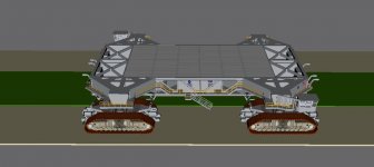
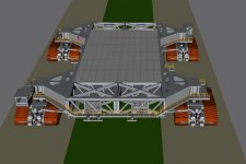
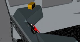
Actually, the drive trucks do turn. The long cylinders you see that connects the trucks with the chassis of the CT is called steering arms. They push/pull the trucks as required to execute the turns.

The key to maneuvering the CT is planning ahead. They actually slow the CT down in the turns while executing gradual increases in turn angle. This technique allows the CT to perform the steep turns required with minimum turning of the trucks required.

---------- Post added at 10:08 AM ---------- Previous post was at 08:58 AM ----------

According to my research the turn radius of the CT is 152 m.

---------- Post added at 06:40 PM ---------- Previous post was at 10:08 AM ----------

If you haven't seen them here's a nice detailed tour of CT-1:

Part 1: [nomedia="http://www.youtube.com/watch?v=IArsG6w9oSo"]YouTube- Inside the NASA Crawler Transporter - PART 1 of 3[/nomedia]

Part 2: [nomedia="http://www.youtube.com/watch?v=TvWz06BvO4A"]YouTube- Inside the NASA Crawler Transporter - PART 2 of 3[/nomedia]

Part 3: [nomedia="http://www.youtube.com/watch?v=1uB5femx858"]YouTube- Inside the NASA Crawler Transporter - PART 3 of 3[/nomedia]

---------- Post added at 06:51 PM ---------- Previous post was at 06:40 PM ----------

CT steering is covered in Part 3 starting at 00:50.

---------- Post added at 10:18 PM ---------- Previous post was at 06:51 PM ----------

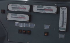
Here's the procedure for starting the move of the CT:


  1. Verify that EXCITER ON indicator is RED lit
  2. Check with ground observer and request clearance to begin move
  3. De-select brakes by depressing the BRAKE PBI
  4. Select desired movement direction by depressing either the FWD or REV PBI(only one can be depressed at any one time)
  5. De-select neutral by depressing the NEUT PBI
  6. Use SPEED CONTROL knob to increase CT speed gradually
  7. Verify brake discs are moving after completing step 6
This is from an episode of the Discovery Channel show "Dirty Jobs", specifically season 3, episode 5 where Mike Rowe goes to KSC and gets familiar with the CT by cleaning/relubing one of the two CTs after which he gets to take the CT out for a short road test.
 
How's the CT coming along?
 
Back
Top