Project Space Shuttle Vessel

I know EVA is not done yet. I know that basically were 2 EVA slide wires. 1 fixed as in STS 5 and one that move with the Payload doors. not sure how they would attach?
I know of 3 versions of slidewires, and actually I was thinking of doing them for the next version.
Meanwhile, and for your situation, maybe consider those fixed slidewires as Bay Bridge payloads... use bay 13 or some other empty bay, and tweak the attachment until it looks good.
 
Maybe someone can explain this. So here is the dimensions for the CBSA (Cargo Bay Stowage Assembly). The box is the right dimensions. But the lower part on the model is longer than the drawing. But the dimension seem correct.
Looking at the image of the Cargo bay from STS5 the drawing matches the length. But why wouldn't the dimension fit? With the correct dimensions one. The lower part fits into the bay.

Also of the shuttle rails. Do we know the distance of the 2 holes near the top? Another thing I never found was how thick was the bay rail adapter
 

Attachments

  • cbsasize2.jpg
    cbsasize2.jpg
    33 KB · Views: 10
  • cbsasize1.jpg
    cbsasize1.jpg
    58.5 KB · Views: 4
  • cbsasize.jpg
    cbsasize.jpg
    46.4 KB · Views: 11
  • cbsassv.jpg
    cbsassv.jpg
    123.4 KB · Views: 10
  • cbsaresized.jpg
    cbsaresized.jpg
    53.8 KB · Views: 13
  • cbsaresized1.jpg
    cbsaresized1.jpg
    73.6 KB · Views: 15
Last edited:
Look at the photo: you have the mounts way too up, thus it all ends up low in the PLB. The mounts seem to be near the middle of the box
 
Do you mean these? The CBSA mounted to a bridge adapter. Looking for the image. I raised it up and raised the PFR
 

Attachments

  • cbsaresized1A.jpg
    cbsaresized1A.jpg
    35.4 KB · Views: 12
  • cbsaresized1c.jpg
    cbsaresized1c.jpg
    107.1 KB · Views: 13
  • cbsaresized1b.jpg
    cbsaresized1b.jpg
    95.8 KB · Views: 12
Last edited:
I think STS 5 is good. There are technical things that would not be there for STS 5. Just saying. Like the slide wire that move with the doors. I know further version that will be an option.

Also STS 5 no eva was performed.

Carrying over payloads from STS and STS2016 may not be totally correct. Due to cargo bay construction and other payload details (IE Payload active/passive fittings). I had to redo meshes.

I know for the Satellite launch there was a whole procedure. I just have a key to open/close the ase doors. Buttons to start the 50 RPM spin and release.

One thing I noticed I couldn't use my mouse to pan around in the cockpit. Maybe User error
 

Attachments

  • sts5ssv3.jpg
    sts5ssv3.jpg
    44.3 KB · Views: 13
  • sts5ssv2.jpg
    sts5ssv2.jpg
    49.5 KB · Views: 12
  • sts5ssv1.jpg
    sts5ssv1.jpg
    45.5 KB · Views: 12
Some help ?
You need the attachment point of the SL vessel to be in the keel trunnion. The manual should help.
Also, you don't need to have the TAA, as it is already included in SSV and configurable in Mission Editor.
 
Many documents here:


This website is in spanish, and you'll probably need to get an account to use the "box" plugin (It's free), but once you're there:

For Space Shuttle, on the scond box called "InfoSondas.com - 2" go to:

"Vuelo Tripulado" -> "Space Shuttle"


Regards.
 
Wow! How did you get into that orbit at MECO? I know the AscentDAP is "limited", but that seems way off. That completely messes up your OMS-1, and then you might even not have enough prop for the OMS-2, let alone the rest of the mission.
For the OMS Assist and SSME Throttles? (and maybe fix the above), here are some better settings (from STS-3) for the I-Loads tab (sorry, still no "nice" UI to change these settings):
1698423349513.png

Looking further at the OMS-2 target orbit, it doesn't match what is in the Mission Editor... did you hit the Save button after Calculate?
 
Looks like you are using D3D9, so the frame rate should be decent... the lower it is, the worst the AscentDAP will perform... I'll launch it to see what I get.

Anyway, one thing to be noted is that the PEG-4 targets aren't perfect, as they don't take into account orbit perturbations, so even with perfect burns the targets will likely be missed by a few NMs, but it should not be anywhere near 50NM like in the images above.
The credit for figuring all of this out, and working the math for the Ascent Target calculator, goes to @indy91. :hailprobe:


I used the STS-1 mission file as a base
So you shouldn't have the OMS Assist (OMSASS = 1 = on, 0 = off)
 
The result looks a bit strange. It seems like the OMS-1 PEG-4 target transferred properly to I-load, but not the insertion targets or the OMS-2 PEG-4 targets. The OMS-2 PEG-4 values are the default ones, maybe that insertion orbit is, too, looks a lot like a direct insertion for a ground-up rendezvous. I replicated all the inputs that @goForTLI did and at least I see that the OMS-1 and OMS-2 I-load show the correct height target (PEG-4 HT) of 160 NM. So I am not really sure how this would happen.

Anyway, one thing to be noted is that the PEG-4 targets aren't perfect, as they don't take into account orbit perturbations, so even with perfect burns the targets will likely be missed by a few NMs, but it should not be anywhere near 50NM like in the images above.

Yeah there is a bit more to do there for non-spherical gravity. I'll get to it eventually. It should be at most a 8 NM error in target altitude right now.
 
I still haven't had time yet to run that launch.... maybe later today.

Yeah there is a bit more to do there for non-spherical gravity. I'll get to it eventually. It should be at most a 8 NM error in target altitude right now.
I'm not complaining in any way, I think it works very well, especially compared with the pre-MECO side. Again, thanks! (y)
 
Finally ran those ascent targets and it seems ok on my end:
state ap/pe PEG-4
-------------------------------------
post MECO 78/+4
tgt OMS-1 155/+51 0/0/160/166
post OMS-1 155/+51
tgt OMS-2 156/+154 0/0/160/346
post OMS-2 156/+154


@goForTLI , it seems like you didn't hit the Save button after changing the parameters and/or didn't re-save the mission and, like @indy91 noted, end up with the default DI OMS targets.

Just to clarify: the Save button in the Ascent tab just transfers the calculated Ascent Targets to the I-Loads (OMS burn data) and the Legacy MECO parameters (the current implementation of the MECO targets). It doesn't actually save the mission, so changing those parameters on an existing mission, still requires the user to re-save the mission, just like if any other parameter was changed.

The user can bypass the Ascent Target calcs, and just input the OMS burn I-loads and (legacy) MECO parameters directly.... but why would anybody do that when there is this powerful tool just a few clicks away?
 
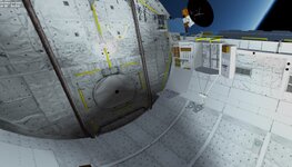
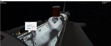
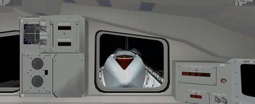
Another quick update!
Progress continues to be made in the display rework, with more and more parts being completed. Managed to hack a calculation of the inertial and relative velocity heading, to feed the HSI during launch, and it is neat to see the inertial velocity being "pulled" in the desired direction as the ascent progresses, something that is very visible in a high-inclination KSC launch or VAFB launch.


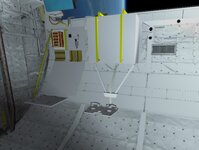
On the OMS/RCS side, lots of work in modules that control the interconnects and dumps. Even though the abort interconnects and dumps will not be available until aborts are implemented, having all those modules now allows me to test (via "hacking") what the OMS/RCS will have to do, in the hopes those subsystems end up capable of all that is needed. Still trying to figure out the logic to ignite the OMS, as that was handled by the MSC module, of which there isn't much info out there.


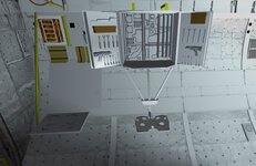
Meanwhile I've opened up a new front of development: MDM improvement. State load/save capability (so the MDM outputs are correct at the start of the sim) is the immediate objective, but I'm also correcting the I/O voltage levels, so the ever-growing signals that pass there can have the correct numbers, thus avoiding (more) problems in the future. Another objective is having the IOMs create the needed Discrete Bundles, and having the subsystems connect where they need, as opposed to having to invent more and more names for Discrete Bundles, and then having to edit the MDMs to connect new signals. This way, any new signals only require work in the subsystem (and GPC software of course). There is another MDM-related issue, this time on the GPC software, where the outputs are reset after being sent to the MDM... an assumption I made a while back that turned out to be wrong. 🤦‍♂️🤦‍♂️ Anyway, not sure I'll fix it in this branch, as the work above is already considerable. Also, no PROMs yet, so I/O will remain 1 word per transaction, but this new setup should make that easier.


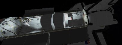
All this will soon slow down to provide time for the v1.8 dev, a release to bridge the gap to v2.0. As promised, I'll look at improving the docking, and regardless of the success of that there are other (smaller) items that will see the light of day.
 
Is there only one RMS camera now (on CCTV)? because end effector's camera could be more useful than elbow's, to see grappling alignment. Also what is grappling procedure, I still tap there and there, but not sure how exactly it works (so far), I use PFTA (forward grapple) in STS-8, with latest 1.7 SSV. (BTW where is R14 panel, mentioned earlier, with CCTV switches).
 
Is there only one RMS camera now (on CCTV)? because end effector's camera could be more useful than elbow's, to see grappling alignment. Also what is grappling procedure, I still tap there and there, but not sure how exactly it works (so far), I use PFTA (forward grapple) in STS-8, with latest 1.7 SSV. (BTW where is R14 panel, mentioned earlier, with CCTV switches).
So, there is only one input* for RMS cameras, but (obviously) 2 cameras in the RMS, and they way this was handled was with the "Port RMS Camera" switch on panel A7U, choosing which camera was being used.
While we are one this, originally only 3 inputs were allocated for PLB cameras and 1 more for each RMS (the flown Port and the never-flown Starboard). Early on they realized that having 4 PLB cameras was very useful, so they started using the Starboard RMS input for a 4th PLB camera, and never looked back.

On the PFTA, what I usually do is take it out of the PLB with one GF, release it, quickly move the EE to the other GF and then bring it back in.
Using the forward GF, first get the correct EE attitude, which should be all 3 angles near 0, then align it with the GF using the EE camera, then just move in and using the Elbow camera check the pin is mostly in the EE.
With the End Effector Mode switch on panel A8U in Auto, just press Ctrl+Enter to grapple and Crtl+Backspace to release.
After grapple, release the PRLAs and translate up and it should come out. Opposite actions to stow.

*) don't blame me, that is the way it was
 
hi, I cannot open payload bay doors, hm, what can that be. I tried it the old fashioned way (R13 panel switches), is computer compulsary now?
And how it was in real life (earlier missions old way, and latest - through computer?)
Actually I had another question before this: I just looked at 51-G mission - there were 3 PAM-D + satellites, and fourth active payload is SPARTAN. but seems only 3 active payloads are supported (as suggested by A6U "rotary" payload latch switch "1-MONITOR-2-MONITOR-3").
P.S. I even imagined optional "scenario" exporter, where shuttle is in "OPF" type position with open payload bay, otherwise it is hard to check payload position. Actually it is how it started, launched, quickly to orbit, and wanted to open PB to see what is right or wrong with payloads...
Yes, following the actual procedures in the Post-Insertion/Generic De-Orbit Prep FDFs for the PLBDs are now required. OPS 202 PRO on CRT4 in SM mode to load the PL BAY DOORS software and then ITEM 1 EXEC to enable enable AC power to the MMCAs that control the door actuators and then ITEM 3 EXEC to enable AUTO MODE. Then two PL BAY DR SYS switches on R13L to ENA. Then PL BAY DR switch to OPEN until TB "OP". Then PL BAY DR to STOP, followed by the two PL BAY DR SYS to DSBL. Then on CRT4, ITEM 2 EXEC to disable AC power again and then OPS 201 PRO to mode back to SM 201 ANTENNA for further on-orbit ops.
 
Back
Top