New Release D3D9Client Development

UPDATE: new improved "A" microtexture available for download

Can you please put your Microtextures doc files into a proper ..\doc\Microtextures subfolder?
oki - will be done in the next release when that insidious "Moon_A texture stripes" effect has been analyzed and fixed. Thx for the hint.

Hi rstr and congrats on the initiative!
... much much more credit for the initiative goes to jarmonik and other D3D9Client developers / idea givers ... I was only supplementing a few hi-res seamless textures for his D3D9Client and achieving official free re-usage grant to resources in the NASA ALSJ image library for Orbiter add-on developers.

Rob

---------- Post added at 02:44 PM ---------- Previous post was at 12:55 AM ----------

You need to create normalmaps and use those photos only to get albedo information...
Thx for your hints. My first attempt for an "A" microtexture normal map is done right now ...
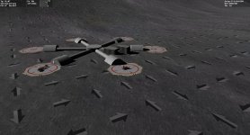
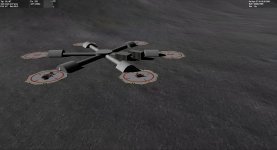
Here's a first screenshot for a replacement A texture (D3D9Moon_A.dds X240) where seamless / mipmap / normal map was applied.

IMHO this is a very realistic texture, obtained from the Apollo 15 mission image archives (AS15-89-12144HR.jpg at ALSJ), with shadows removed by area cloning, and processed to allow seamless tiling.

This "A" microtexture version X240 is attached below. Just copy this variant of D3D9Moon_A.dds into your Texture folder, replacing the previous one.

4throck, I am not very experienced in texture making, so despite reading about normal maps I am quite unsure if I did the correct processing. I used Gimp to generate the DTX5 mipmaps, and then just applied the filter=>map=>normalmap processing, with a scale of +5. But as of now I am lost in how to define and adjust the albedo on a normalmap so it doesn't look all reflective white; only kludge I have found was to switch-on option Swap RGB to achieve the above result. Any hint welcome as googling didn't help me in catching the idea .. I am still learning. And secondly, I still have doubts whether a normal map / heightmap makes sense for the 0..60 meters altitude AGL at all for depicting just small scattered rocks, and whether this normalmapping is even supported by the microtexture feature in D3D9 shader program. Thx for your lenience with a newbie's dumb questions in texturing.

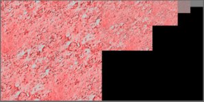
There appears to be some visible stripes between 200m-3k. ... Those are likely coming in from the _A texture.
There is a rasterizing effect present, almost drawing a grid of lines on the surface at a certain distance. I think it's coming from a shadowed border of the low-altitude tiles
IMHO it is a side effect from the repetitive tiling of the A texture; if there is any pattern in the texture that has a unique feature like being even slightly brighter than other areas then the repetitive tiling will convice the eye that there are two stripes along each tiling axis. Now, any interesting texture must differ from dull uniform grey .. which means that no matter how seamless the texture is we will always see some feature being recognizably repeated endlessly in two directions. As of now the A texture is 2048x2048 but even this size cannot avoid the stripe effect. Suggestions very welcome.
 

Attachments

Last edited:
Say, Jarmonik, do you think it's possible to fix the huge texture distortions at the poles for the microtextures?

IMHO it is a side effect from the repetitive tiling of the A texture; if there is any pattern in the texture that has a unique feature like being even slightly brighter than other areas then the repetitive tiling will convice the eye that there are two stripes along each tiling axis.

I am aware of the tiling effect, but the previous texture had a clearly visible border.

As of now the A texture is 2048x2048 but even this size cannot avoid the stripe effect. Suggestions very welcome.

It's impossible to get rid of it entirely. Most games don't have the problem because you're not supposed to look at them from that altitude. The only technique I know of to avoid the effect is to start fading them out from a certain threshold up. It creates its own artifacts, but they're usually less intrusive.

IMHO this is a very realistic texture, obtained from the Apollo 15 mission image archives (AS15-89-12144HR.jpg at ALSJ), with shadows removed by area cloning, and processed to allow seamless tiling.

It's good work, but visually a bit too busy for my tastes. I like the old ones better, save for that border pehnomenon...

---------- Post added at 09:57 PM ---------- Previous post was at 09:12 PM ----------

Played around with it for over 30 minutes, and I think it's definitely too busy. It's so busy it drowns out the mid-altitude texture. It's hard to make out among the noise...

@Jarmonik: I get a crash after zooming out and back in a few times. Is it possible there's a memory leak in connection with the microtextures?
 
Last edited:
4throck, I am not very experienced in texture making, so despite reading about normal maps I am quite unsure if I did the correct processing. I used Gimp to generate the DTX5 mipmaps, and then just applied the filter=>map=>normalmap processing, with a scale of +5...

...As of now the A texture is 2048x2048 but even this size cannot avoid the stripe effect. Suggestions very welcome.

Regarding the stripes:

- The texture should be pretty homogeneous without large lighter nor darker areas than the rest of the texture. The latest texture shows a darker region and lighter region, which makes the pattern well visible.

- Lower mipmaps can be shifted towards plain grey to remove the stripes. But that will also remove more distant details. (See screen shot)

- Due to high contrast in _A texture, the _B texture can't help much to hide the pattern and the _A texture breaks through.

Normal maps:

Unfortunately that's not correct. There exists no filter, that I know of, that could accomplish the task properly. So, you would need some kind of sculpture tool to transform the 2D image into a 3D terrain / mesh. Then a proper normal map could be generated if the sculpture tool supports that.

Also, if you find luna like terrain outdoors then normal map can be generated by means of photography and control of light direction.

EDIT: Normal maps can also be generated from a height map. Without a better tools that's likely the way forward. Height map is a grey scale image where a lighter color represents higher terrain and darker lower terrain. There should exists plenty of tools to convert height map to normal map.
 

Attachments

  • Mips.jpg
    Mips.jpg
    30.7 KB · Views: 19
Last edited:
Say, Jarmonik, do you think it's possible to fix the huge texture distortions at the poles for the microtextures?

@Jarmonik: I get a crash after zooming out and back in a few times. Is it possible there's a memory leak in connection with the microtextures?

The tile size and aspect ration is currently not taken in account. It's easy to implement, no problem there. I'll get that sorted out.

Could the CTD be this one:

http://www.orbiter-forum.com/project.php?issueid=1217

I am not seeing any memory leaks there. You can see the statistics by pressing Ctrl + Shift + C (that's left Ctrl & Shift)
 
Last edited:
The tile size and aspect ration is currently not taken in account. It's easy to implement, no problem there. I'll get that sorted out.

Very cool! :cheers:

Could the CTD be this one:

Very possible, at least he symptoms seem he same. Except I don't even need the time acceleration.
 
Very possible, at least he symptoms seem he same. Except I don't even need the time acceleration.
Are there any D3D9 specific errors printed in Orbiter Log ?
 
Nope. Guess I could run it from source and crank up the log level, but I have to sign off for the night. Maybe tomorrow, if I find some time in school :lol:
 
EDIT: Normal maps can also be generated from a height map. Without a better tools that's likely the way forward. Height map is a grey scale image where a lighter color represents higher terrain and darker lower terrain. There should exists plenty of tools to convert height map to normal map.

Correct. That's the way to go. Here's a lunar heightmap in JPG format: http://pdsimg.jpl.nasa.gov/data/lro...irtanen2/NAC_DTM_VIRTANEN2_E180N1810.PYR.jpeg

and an image of the same area: http://pdsimg.jpl.nasa.gov/data/lro...nen2/NAC_DTM_VIRTANEN2_M145793402_2M.PYR.jpeg


Both come from here:
http://pdsimg.jpl.nasa.gov/data/lro/lroc/rdr/lrolrc_2001/extras/browse/nac_dtm/virtanen2/


If you only have 2D images the best solution is to hand paint high/low areas with white/black. That means a dark circle for each crater, a white area for each boulder, and gray scale for everything in between... tedious but effective.
 
Last edited:
Regarding the stripes:
- The texture should be pretty homogeneous without large lighter nor darker areas than the rest of the texture. The latest texture shows a darker region and lighter region, which makes the pattern well visible.
- Lower mipmaps can be shifted towards plain grey to remove the stripes. But that will also remove more distant details. (See screen shot)
- Due to high contrast in _A texture, the _B texture can't help much to hide the pattern and the _A texture breaks through.

Normal maps can also be generated from a height map. Without a better tools that's likely the way forward.

Okay, I got the point. "Going forward" then in a couple of days ..:)

I am aware of the tiling effect, but the previous texture had a clearly visible border.
New A-texture: Played around with it for over 30 minutes, and I think it's definitely too busy. I like the old ones better, save for that border phenomenon...
Here's what I'm gonna do:
1) I'll provide different alternative microtextures to choose from, e.g. D3D9Moon_A1.dds, ... D3D9Moon_A3.dds, D3D9Moon_B1.dds ... so anyone can simple copy and past whatever the person likes best to the runtime A/B/C dds file.
2) As explained by 4throck and jarmonik, I will generate a new alternative normalmapped texture set from heightmaps that I will create via Povray; I have used this approach some time ago, and just need to change the procedural sources a bit for achieving crater and stone effects in random locations. I'll publish the sources then as well within the next release.

So stand-by for news in a couple of days :jiggy: Rob
 
Last edited:
Now, any interesting texture must differ from dull uniform grey .. which means that no matter how seamless the texture is we will always see some feature being recognizably repeated endlessly in two directions. As of now the A texture is 2048x2048 but even this size cannot avoid the stripe effect. Suggestions very welcome.

Would it be possible to randomly mirror and/or rotate the microtexture in adjacent tiles to break up the pattern? I guess this is more a question to jarmonik since it involves randomizing the texture coordinates of the mesh patches, rather than manipulating the texture itself.
 
Or combining the two techniques, which would require twice as much textures, but the technique of randomizing microtextures was great and was doing a great job at hiding the patterns.
 
"Almost stripeless" old-style _A texture replacement for download

I am aware of the tiling effect, but the previous texture had a clearly visible border.
I like the old ones better, save for that border pehnomenon...
As intermediate solution, plz find an almost stripeless "old-style" [email protected] below for replacement.
I hope this is jedidia after installing [email protected] :jj: lol

(P.S.: The full microtexture download published in #3473 has been updated (V1.1) to also contain the "almost stripeless" _A. The original screenshots in #3473 will still suffice. I didn't care though to re-run my Hadley-Approach video with the _A V1.1.)

Enjoy - Rob

ATTN: New info, see #3502 .., next _A version to follow soon
 

Attachments

Last edited:
...I will generate a new alternative normalmapped texture set from heightmaps that I will create via Povray...

Great! That would be an interesting discussion for another topic: physical parameters for realistic generation of different planetary surfaces (crater density, depth, size, etc)

---------- Post added at 15:21 ---------- Previous post was at 15:15 ----------

Or combining the two techniques, which would require twice as much textures...

Well, just for the sake of discussion, we could have different textures according to rock/crater density, and simply vary those according to a surface roughness map...

That would get you random textures and a better approximation to the actual terrain characteristics.

Of course, it would complicate things with multiple textures at multiple scales. But that's the way the MS FlightSim guys solved the problem long ago (using "landclass" files)
 
That would be an interesting discussion for another topic: physical parameters for realistic generation of different planetary surfaces (crater density, depth, size, etc)
Yup ... have a look here:
http://space3d.no.sapo.pt/article_asteroid.html
The "crater" 3D models wrapped there onto isometric surfaces were also generated by a procedural generator for heightfields .. see "asteroid_virtual.inc" source. As mentioned earlier, long time ago in the "Orulex" days, I used such an approach for rendering a moon landscape. Of course, we just utilize a Povray heightfield generator part, not the full rendering code. I'll keep you informed...
Cheers - Rob
 
Last edited:
Would it be possible to randomly mirror and/or rotate the microtexture in adjacent tiles to break up the pattern? I guess this is more a question to jarmonik since it involves randomizing the texture coordinates of the mesh patches, rather than manipulating the texture itself.

That's sounds like a good idea. Here are some experimental results:

If the tiles are rotated then the pattern is reduced and the tiles look good from a close distance.

If random mirroring is added then the pattern will disappear from a distance but a close range rendering shows annoying mirror effects on ground here and there.

This code section has been added to Surface.fx to do the rotations:
PHP:
// Noise texture size 128x128, 512/128 = 4
float fRot = tex2D(NoiseTexS, UVn*4.0f).r;
			
if (fRot<0.5f) UVr = UVr.yx;						// Rotate 90deg and mirror
if (fRot<0.35) UVr = -UVr;							// Rotate 180deg
if (fRot>0.65) UVr = -UVr;							// Rotate 180deg

PHP:
if (bMicro) {

float dist = frg.aux[AUX_DIST];// / fAlpha;

float2 UVn  = frg.texUV.xy;
float2 UVr  = frg.texUV.xy;

// Noise texture size 128x128, 512/128 = 4
float fRot = tex2D(NoiseTexS, UVn*4.0f).r;
float fMir = tex2D(NoiseTexS, UVn*4.0f+0.5).r;

if (fRot<0.5f) UVr = UVr.yx;						// Rotate 90deg and mirror
if (fRot<0.35) UVr = -UVr;							// Rotate 180deg
if (fRot>0.65) UVr = -UVr;							// Rotate 180deg

//if (fMir<0.4)  UVr.x = -UVr.x;						// Mirror X
//if (fMir>0.6)  UVr.y = -UVr.y;						// Mirror Y

float3 cFar = tex2D(MicroCS, UVn*8.0f).rgb;			// High altitude micro texture C
float3 cMed = tex2D(MicroBS, UVn*64.0f).rgb;		// Medimum altitude micro texture B
float3 cLow = tex2D(MicroAS, UVr*512.0f).rgb;		// Low altitude micro texture A

float step1 = smoothstep(25000, 12000, dist);

float3 cFnl = (cFar+0.5f) * (cMed+0.5f) * (cLow+0.5f);

// Approximate normals
float3 cNrm  = float3((cFnl.xy - 1.0f) * 2.0f, 0) * step1;
cNrm.z  = cos(cNrm.x * cNrm.y * 1.57);

// Approximate world space normal
//nrmW = normalize((vTangent * cNrm.x) + (vBiTangent * cNrm.y) + (nrmW * cNrm.z));

// Apply luminance
cTex.rgb *= lerp(1.0f, cFnl.b, step1);
}
 

Attachments

Well, just for the sake of discussion, we could have different textures according to rock/crater density, and simply vary those according to a surface roughness map...

That would get you random textures and a better approximation to the actual terrain characteristics.

With a use of texture arrays in DX10+ it's doable. But in DX9 it's a little more troublesome since each texture needs to be fed to the pipeline separately, but should be still possible. Also, an other option worth of investigating is to pack multiple terrain types in one texture. Like having four 1024x1024 textures in one 2048x2048 texture. Texture WRAP would no longer work but I see no reason why it couldn't be replaced with programmed functionality.

Terrain slope factor is know to a pixel shader and can be used. Also, I am currently running some experiments to add a mesh based rock formations on the surface. Getting that to work would allow to snap shadows and some surface base objects to the terrain as well.
 
Last edited:
This code section has been added to Surface.fx to do the rotations:

That was quick :thumbup:
Good to hear that the rotations improve the banding. Interestingly, in the image there is still some banding evident at larger distances, so it's not a complete cure.

I wonder if it would be worth high-pass filtering the microtexture (offline, not on the fly by the client!). I guess it's the lower spatial frequencies in the microtexture that are responsible for the banding at large distances. At least the filter should cut all frequencies below what is already covered by the underlying global texture, so that the microtextures only show the close-up high frequency stuff, but don't add low-frequency bias.

Edit:
As of now the A texture is 2048x2048 but even this size cannot avoid the stripe effect. Suggestions very welcome.

Increasing the texture size won't to anything to improve the stripes, unless you also increase the area over which the texture is applied. It's the low frequencies, not the high ones that are the problem here.

Just increasing the texture size will only make a difference when you get very close. In fact, I would guess you have to get really close for the 2048x2048 textures to make any difference.
 
I wonder if it would be worth high-pass filtering the microtexture (offline, not on the fly by the client!). I guess it's the lower spatial frequencies in the microtexture that are responsible for the banding at large distances.

You`ve hit the bull's eye! Just found this most interesting info fully supporting your thesis:
the_power_of_the_high_pass_filter.php
I'll be providing an appropriate _A texture by tomorrow.
Rob
 
Last edited:
Back
Top