News The Space Shuttle for Flightgear 3.6

GLS

Well-known member
Orbiter Contributor
Addon Developer
Joined
Mar 22, 2008
Messages
5,917
Reaction score
2,921
Points
188
Website
github.com
... and now I can do optimized de-orbit PEG-4 fits.

The input for this is a trial PEG-4 target set (where TIG just marks the beginning of the search interval), a landing site (lat, lon) and the desired REI to the site, the fit then automatically adjusts TIG such that the REI target is met and at the same time optimizes the thetaT angle such that basically only a prograde burn is needed.

This gets me into an EI with the desired REI, altitude and flightpath angle as per c1/c2 at typically < 40 iterations even from a fairly eccentric orbit in J3 gravity (taking into account Earth rotation and shape of course).

Is the cross-range taken into account? You might have a solution that has a acceptable range at EI, but the vehicle might not be heading to the landing site... :facepalm:
 

Thorsten

Active member
Joined
Dec 7, 2013
Messages
785
Reaction score
56
Points
43
That case can be recognized as an ill-posed fit problem and the solver can simply refuse to process it. You can check for closest approach of groundtrack to site before starting any fits (that's to a good approximation just a spherical trigonometry question) and only run the fit when this distance is acceptable.

Generally though, I don't envision this as a tool for novice users who want to know what to push to de-orbit now (I have that kind of tool with my Shuttle code), this is rather for people who basically know what they're doing and recognize pathological solutions themselves.

Even more generally, I'm not sure how much Shuttle specifics (like a particular cross range) I should code into this, because the targeting is of course more general than just Shuttle.
 

Thorsten

Active member
Joined
Dec 7, 2013
Messages
785
Reaction score
56
Points
43
In other matters - right before Christmas, the next update of the Flight Manual is ready for download.

flight_manual_standard.png


This brings the documentation up to speed with the latest milestone 9 which includes the simulation of IMU alignment and DPS management procedures, 3EO contingency aborts, droop guidance for late 2EO scenarios, the BFS, the Shuttle Carrier Aircraft, the approach trainer function and much more.

As usual, Flightgear users can get the standard edition for free. All previous download credentials for the Deluxe edition remain valid.
 

Thorsten

Active member
Joined
Dec 7, 2013
Messages
785
Reaction score
56
Points
43
There's now a working burn solution tool which can do optimizations and provide PEG-4 and PEG-7 targets.

Here's an example for an insertion burn - the tool gets the Shuttle state vector after MECO, and in the following two optimizations over PEG-4 targets are requested...


Code:
input

config

units imperial
time_format plain
gravity_model J3
earth_model IERS
burn_model constant
plot2d_resolution 400
fit silent
max_time 10000
fit_max_iterations 100
time_format MET

state_vector

x 21425960.92
y 62204.24
z 55720.39
vx 0.0
vy 18844.65
vz 17314.01

met 000/00:12:00

landing_site
name Testsite
lat 0.0
lon 0.0

launch_site
name Testsite
lat 0.0
lon 0.0


burn_peg4
name Insertion1
time 400.0
thetaT	170.0
H 185.0
c1 0.0
c2 0.0
optimize theta
ops 1

burn_peg4
name Insertion2
time 2800.0
thetaT	340.0
H 185
c1 0.0
c2 0.0
optimize tig
ops 1


output

list
orbital final

plot2d
file shuttle_insertion.dat	
x time
y altitude

end

... and the tool spits out the ignition times and the PEG-4 and PEG-7 parameters for the burns such that the insertion target is reached and any radial components are minimized. The theta-T angles are all given relative to the launch site because the OPS 1 definitions were selected above.

Code:
Reading shuttle_insertion.cfg for configuration.
Using imperial units.
Adding site Testsite at lat 0 and lon 0
Site Testsite is defined as launch site
Adding PEG-4 burn
PEG-4 targets: thetaT 170 H 342620 c1 0 c2 0
Using OPS 1 angle definitions for burn Insertion1
Adding optimized PEG-4 burn
Using OPS 1 angle definitions for burn Insertion2

Parameters of burn: Insertion1
TIG             : 000/00:18:40
PEG-4
H               : 185
theta T         : 210.439
c1              : 0
c2              : 0
PEG-7
Dx (prograde)   : 244.871
Dy (normal)     : 0
Dz (radial)     : -0

Burn Insertion1 finished, burn duration was 159.12 seconds.

Parameters of burn: Insertion2
TIG             : 000/01:02:32.6
PEG-4
H               : 185
theta T         : 340
c1              : 0
c2              : 0
PEG-7
Dx (prograde)   : 170.224
Dy (normal)     : 0
Dz (radial)     : -0.287268

Burn Insertion2 finished, burn duration was 110.61 seconds.
Radius [nm]:             3628.01
Alt. above surface [nm]: 187.828
Apoapsis [nm]:           188.299
Periapsis [nm]:          187.441
Speed [ft/s]:            25269.4
Longitude [deg]:         -91.6732
Latitude  [deg]:         -34.7692
Semi-major axis [nm]:    3627.93
Eccentricity:            0.000118192
Inclination [deg]:       42.5454
Asc. node lon. [deg]:    359.256
Arg. of periapsis [deg]: 202.092
True anomaly [deg]:      100.409
Plot written to shuttle_insertion.dat!

I think these targets ought to be good to be punched right into the MNVR display.

I'm ready to release the software in this stage, but I still need to add a bit of supporting documentation. I'll start a new thread tomorrow introducing the tool in a bit more detail.
 

GLS

Well-known member
Orbiter Contributor
Addon Developer
Joined
Mar 22, 2008
Messages
5,917
Reaction score
2,921
Points
188
Website
github.com
One nitpick: the OMS-1 burn should be fixed at MECO+120s and not at 18mins MET (which I assume is the apogee).
Which brings another question to mind: if the vehicle is rising at OMS-1 (FPA > 0), is the burn full prograde or not? (and if not, is it thru the velocity vector at ignition or what?)
 

Thorsten

Active member
Joined
Dec 7, 2013
Messages
785
Reaction score
56
Points
43
One nitpick: the OMS-1 burn should be fixed at MECO+120s and not at 18mins MET (which I assume is the apogee).

It's a tool - it does what it's asked to. In the event, I asked it to find me the optimal burn to 185 miles altitude given the current vehicle state and the ignition time of 400 seconds post-simulation start. That it did.

If you ask it to find a burn for MECO+120 at fixed theta, it will do that as well.

Which brings another question to mind: if the vehicle is rising at OMS-1 (FPA > 0), is the burn full prograde or not?

That's the point of the optimization fit (and the beauty of numerical solutions) - it determines the conditions under which you can do a fully prograde burn (which minimizes the Delta v required). Generally you can achieve that if you free either TIG or ThetaT (unless you're asking for a pathological target), but if you fix both you will have a radial component unless you happen to hit the right spot accidentially (its not a global optimum, mind - that is reached for burns at the apses - it's an optimum under an additional constraint).

The situation you have in mind might well require a radial component (if you're 'reasonably close' to a good solution, the radial component is small enough such that the difference in total Delta v is pretty much negligible).

And to my knowledge, the definition of 'prograde' is 'through the velocity vector' (the velocity vector changes during a finite-duration burn, the computation assumes that spacecraft attitude follows the velocity vector and is not fixed - though for the burn durations of the Shuttle and the fact that the attitude deadband for the OMS burn is 10 degrees, the difference seems academic).
 
Last edited:

GLS

Well-known member
Orbiter Contributor
Addon Developer
Joined
Mar 22, 2008
Messages
5,917
Reaction score
2,921
Points
188
Website
github.com
And to my knowledge, the definition of 'prograde' is 'through the velocity vector' (the velocity vector changes during a finite-duration burn, the computation assumes that spacecraft attitude follows the velocity vector and is not fixed - though for the burn durations of the Shuttle and the fact that the attitude deadband for the OMS burn is 10 degrees, the difference seems academic).

Yes, when I said prograde I meant horizontal, or just dV in X.
 

Gingin

Member
Joined
Feb 5, 2015
Messages
270
Reaction score
23
Points
18
Location
City of Light
Missed the released of your new Manual, I will download that :)

Still need to test that very nice computations tool, might edit the wiki after if I understand it correctly :)
 

Thorsten

Active member
Joined
Dec 7, 2013
Messages
785
Reaction score
56
Points
43
The Shuttle now (finally) supports PEG-4 targeting for the de-orbit procedure - after entering the parameters and asking for a solution, the computer will take a few seconds and eventually spit out the PEG-7 set for the chosen target.

peg4_targeting01.jpg


Also, the MCC comm dialog now allows to capture a state vector snapshot which can be used by a software like LEO targeting to do a fit for the optimal PEG-4 ignition time and transfer angle.

For pathological parameters, the fit will either yield ridiculously high Dz (radial velocity component) or plainly not converge.

PEG-4 for insertion and automated target generation for the ATO procedure is to follow soonish (took a while to benchmark the numerics properly...)
 

Thorsten

Active member
Joined
Dec 7, 2013
Messages
785
Reaction score
56
Points
43
It's been some time, but the Shuttle is still progressing.

One development front is a revamp of the dialogs - I've been exploring the canvas technology for an UI, and the result is rather pleasing. There's now customized propellant dialogs which show the location of the tanks, the MDU screens could be detatched before, but when they're rendered as an UI dialog, they act as touchscreens down in the menu area, so one can completely navigate through the MEDS part without the cocpit edgekeys - and the keypad has been replaced by a photo-realistic version.

I'll gradually convert the dialogs to the new style and phase out the old technology.

shuttle_dialogs.jpg


PEG-4 targeting as the 'lite version' of the LEO targeting code is now implemented for OMS-1, OMS-2 and de-orbit burns, I haven't tested this extensively in-sim but the results looked reasonable and check out against what LEO targeting produces for the same state vector.

The newest development is something to make all the different valve switches actually useful - a leakage simulation.

It's now possible to make the propellant distribution system leak at any point (e.g. the oxidizer crossfeeding manifold) and all connected tanks will then be drained as long as they're connected. In the example above, both closing the crossfeed valves or the tank isolation valves will stop the fuel loss.

It's also possible to simulate multiple leaks, for instance a leak of the tank and a leak of the distribution manifold will respond to closing the tank isolation valves by reducing the fuel loss to what's lost from the tank itself, but that can't be affected by any valve operation.

All this opens another interesting front for training failure scenarios...
 

Gingin

Member
Joined
Feb 5, 2015
Messages
270
Reaction score
23
Points
18
Location
City of Light
Hey guys, one of my last flight with the Shuttle working on some contigency abort to Bermuda.
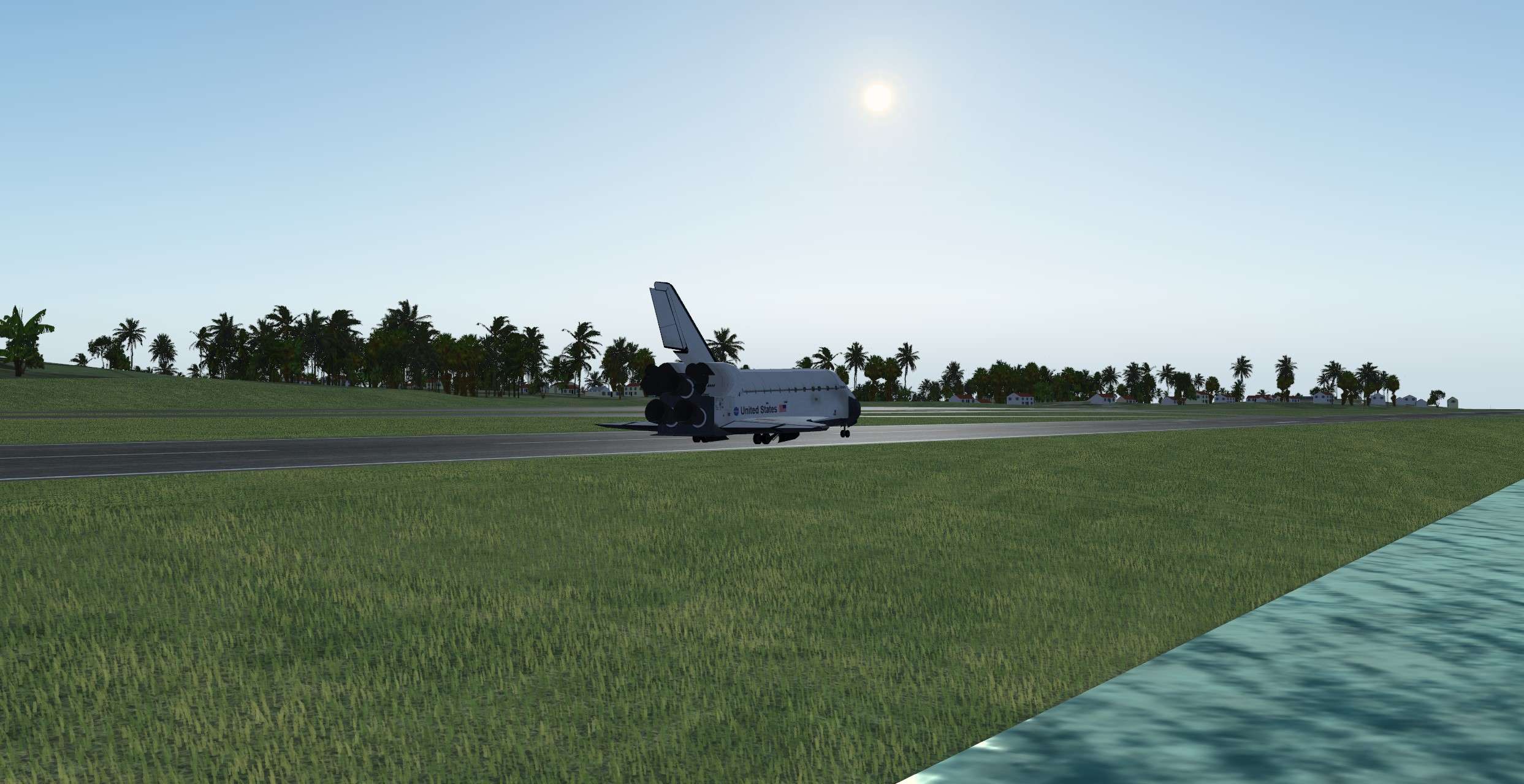
Made it finally :)

It might have been the shortest space flight of the last decade.
Less than 20 mn to reach Bermuda Island at Mach 10.

But it wasn't supposed to be like that, I didn't expect to end my first Shuttle flight as a Commander like that.

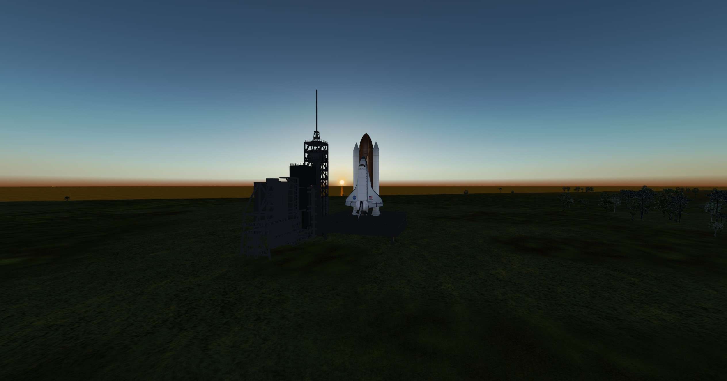
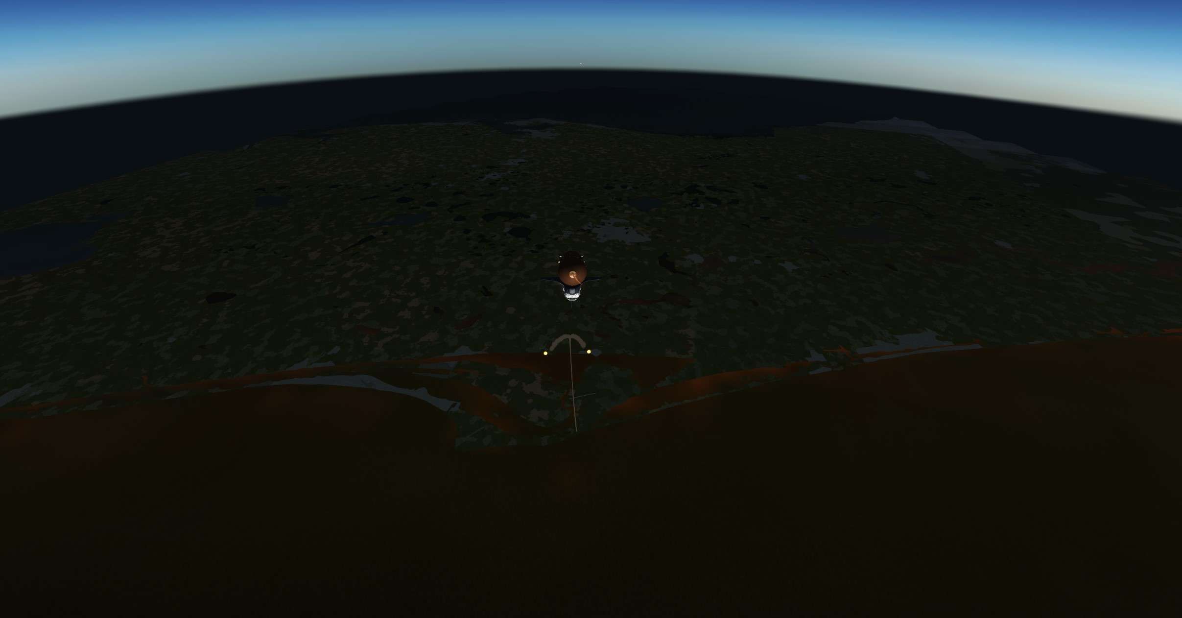
Everything started on a warm morning of may, Sunrise at horizon, everyone settled and restrained in their seats.
Almost ready to go for a maintenance mission to Hubble.
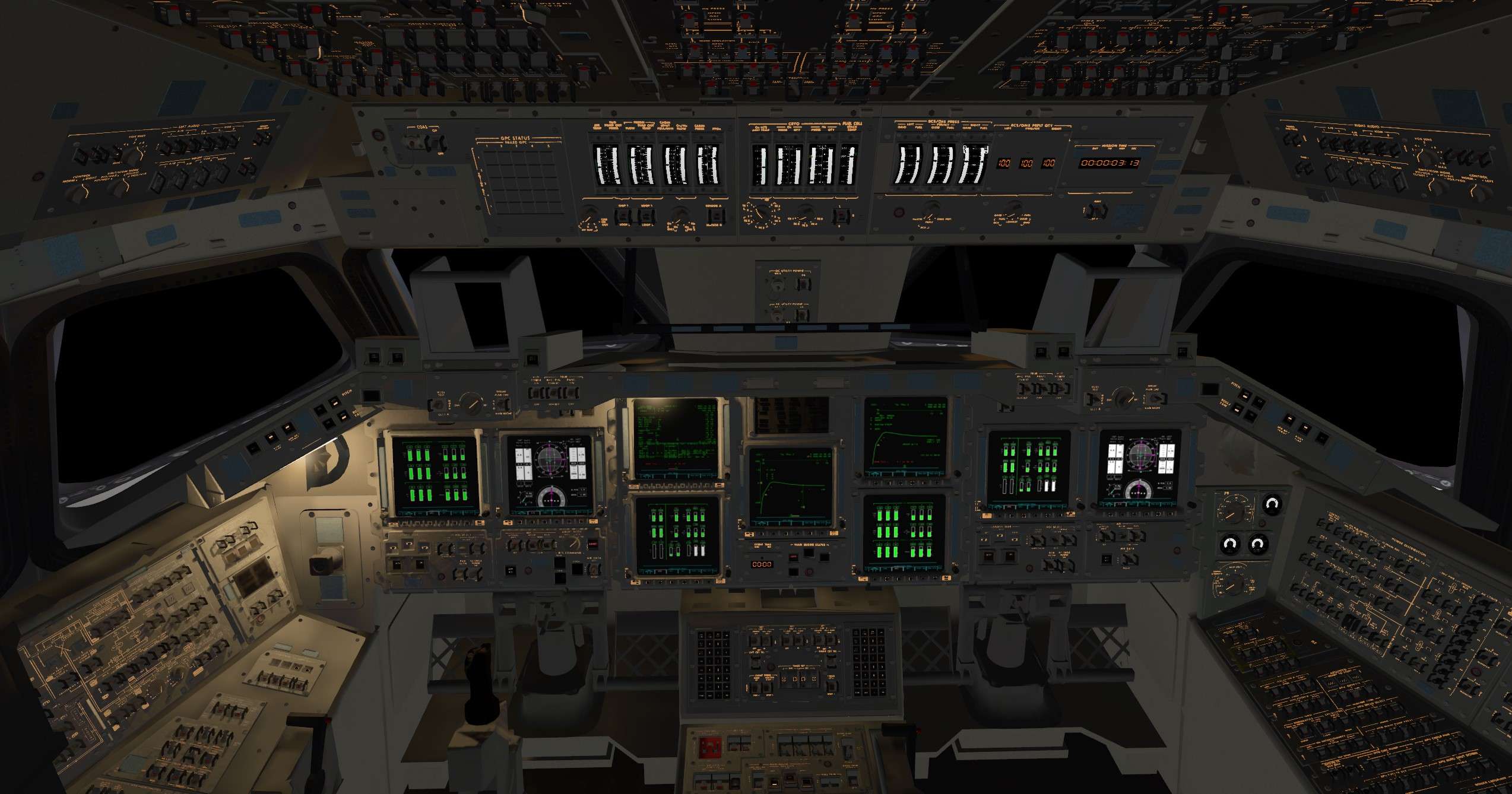
APU started, final countdown started. From now on, we have to monitor our gigantic fuel trap, and think fast in case of failure.
All the cameras are turned towards the Pad

hAeAgz.jpg


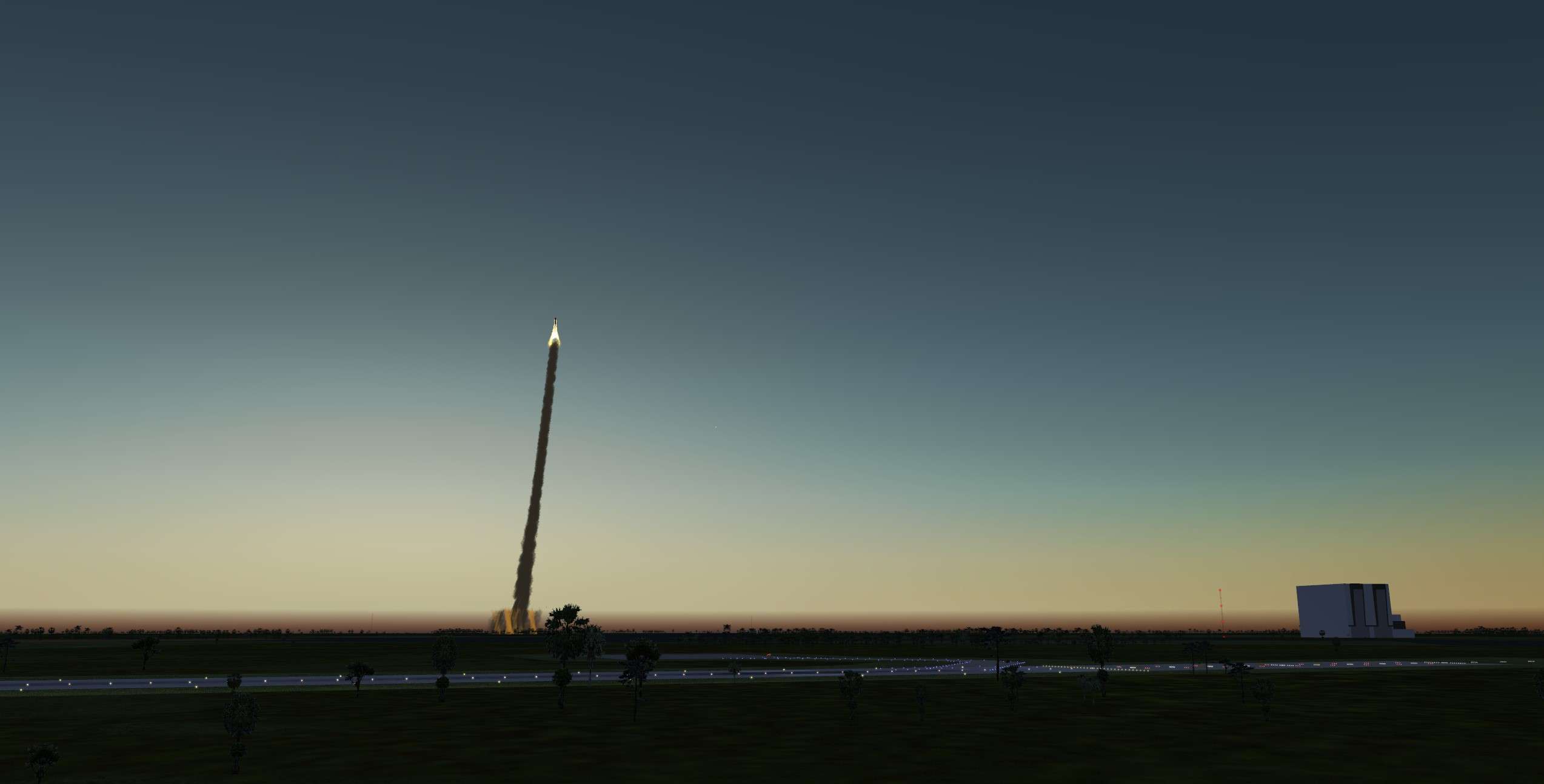
We have a go for Launch, SRB ignition followed by Main Engines ignition, 3 G's in our face for 2 mn. Let's breath and relax.

Q97gDD.jpg


First stage of ascent, so critical. Bucket Ok, everything looks good.
The Orbiter is shaking like hell. Hopefully, SRB separation is gonna occur soon.
Bye Bye KSC


Asiwhz.jpg


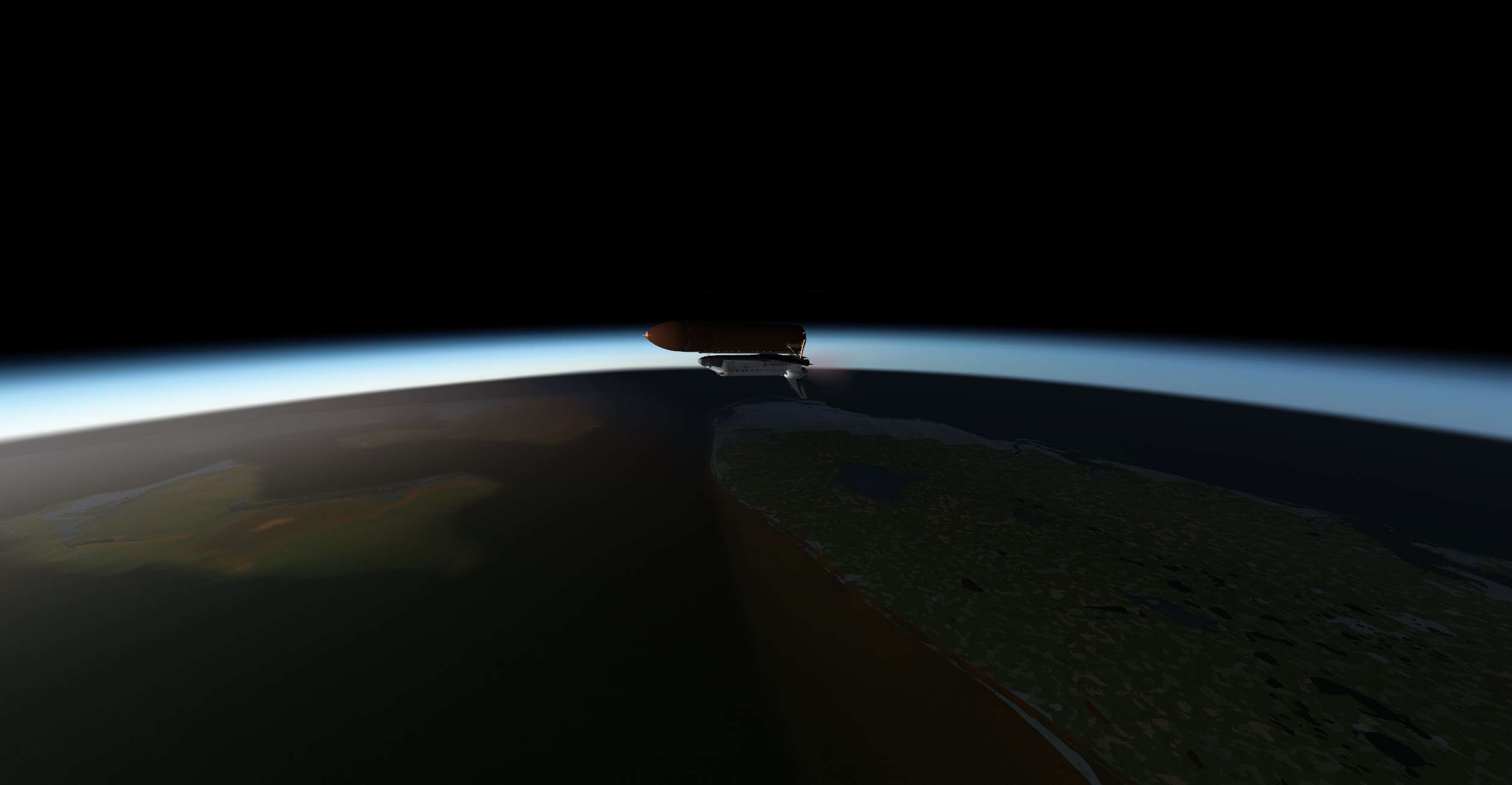
Hello Second stage of ascent, more peacefull in appearance.
Sun is rising, but we are still 5 mn from MECO, let's focus.
My hand is never far from the Abort Switch, in case you know..

17mZ8I.jpg


BAM, Master Alarm, Left Engine failure. My hand is sweating now, and I have to get rid of that startle effect.
MCC gave us its Instruction.
Atlantis , Go TAL abort to Banjul.
No time to think, they know better what is best between a RTLS and a TAL.
TAL and abort switch pressed.
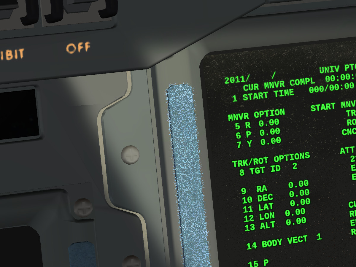
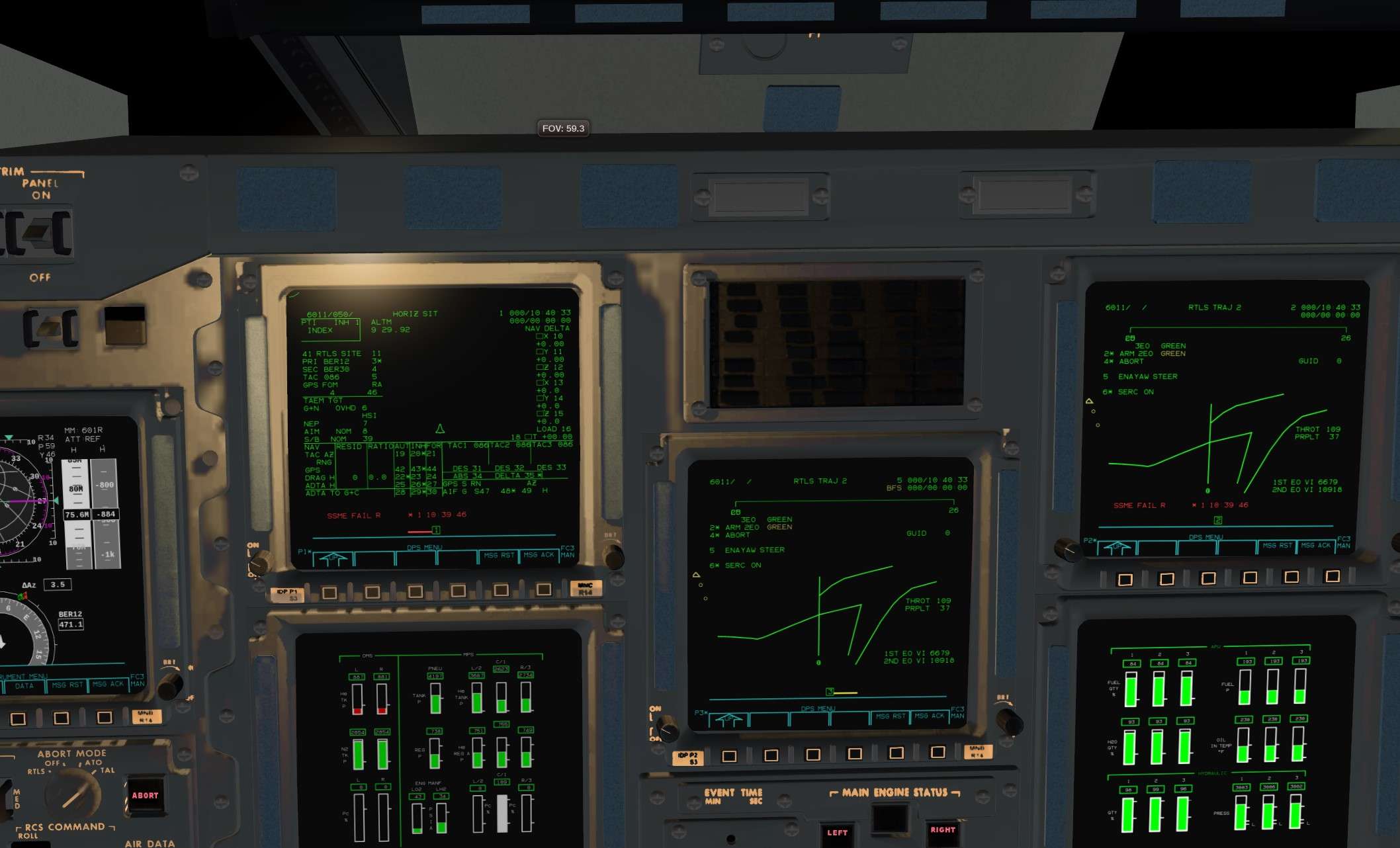
GPC change and display a screen that I would have never think to see for real.
Damn, it is happening


qs4TAc.jpg


Dump started, crossfeed valves opened, and OMS propellant is going out like expected.
Not too bad in our sadness

ikdrDU.jpg


Almost at 10000 feet per second, or Mach 10. Nothing new, I read again my checklist for the TAL abort.
Parameters are good.

What now? Another Master Caution, we lost the right engine , and it's not good at all.
Droop altitude is flashing, we are not gonna do it before 265000 feet.
Few seconds to think with my pilot and Mission specialist, we have to go into our contigency abort for 2 engine out.
We should be ok for Bermuda Island or a Bailout.
MCC confirms, go EO 2 Green Bermuda abort.
Roger that MCC.

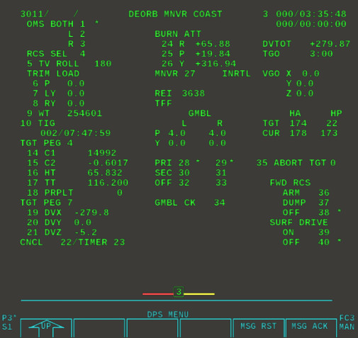
Again another screen configuration, what a day. Am I in the sim or is it for real ?

MaOL4P.jpg


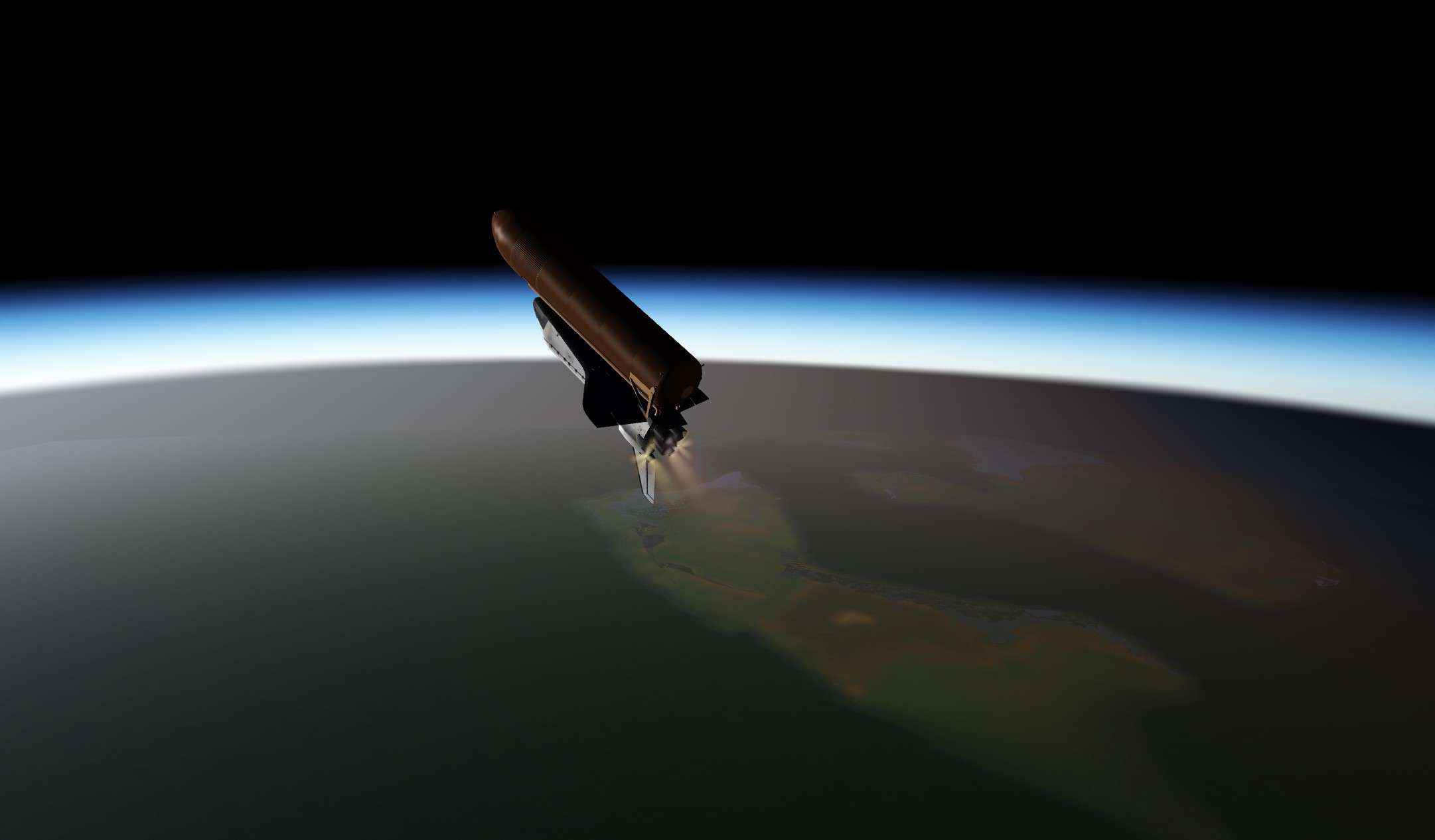
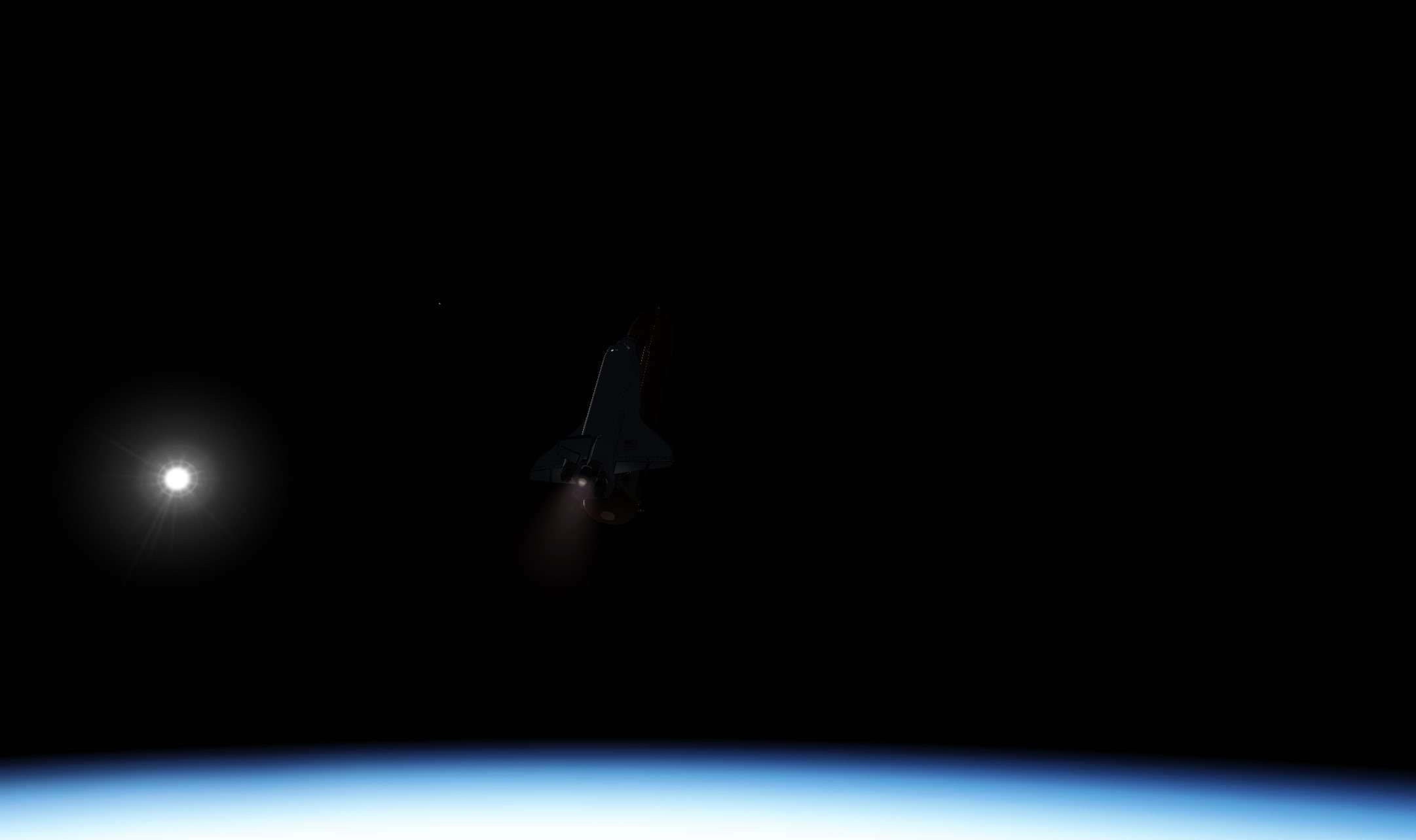
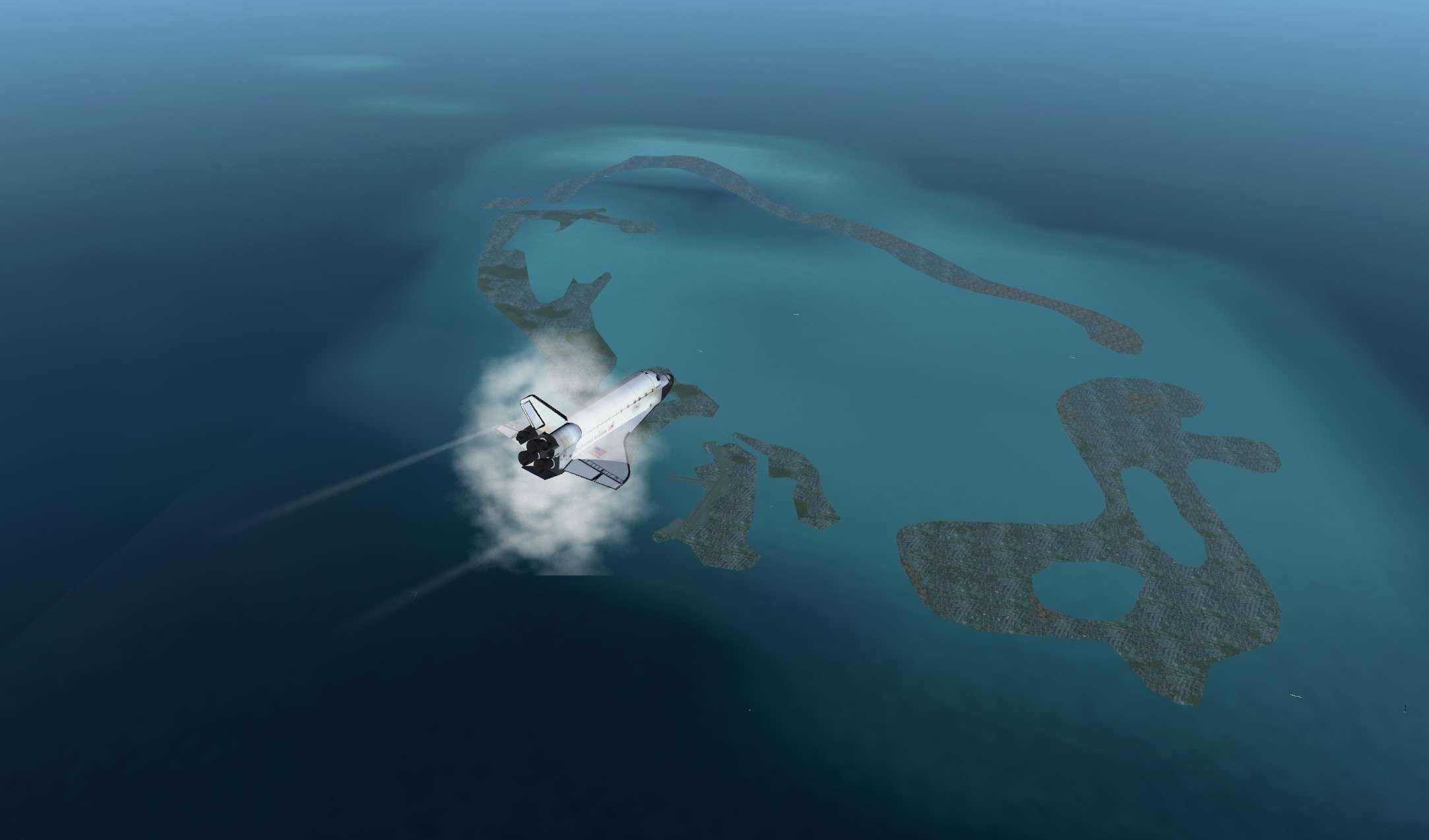
We are diving like hell into atmosphere, and our only remaining engine is struggling to give us enough vertical speed to not Over G during entry.
Let's have faith in the procedures, after all, NASA guys are top notch...


ydtsUt.jpg


280000 feet and diving again, MECO and External Tank fast separation before 265000 feet. We are already in higher layer of atmosphere.
50 degrees of angle of attack, Nz to hold at 3.8 G. AP is working well.
Propellant dump is occuring, good.
I am starting to believe we might survive that one. We should avoid the lethal 4.1 G boundary.
I advise my mates that we might black out a bit during that phase.
Here we are, let's pray

8IdAyh.jpg


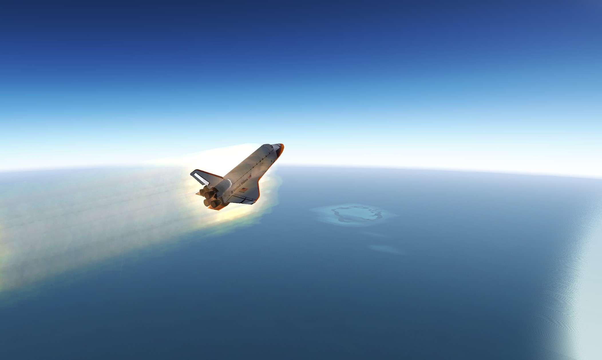
Phew, we survived the trickiest phase of this abort. Shuttle Ok.
At least now, we can write for sure that the Shuttle can survive 4 G. It's not anymore an engineering thing.

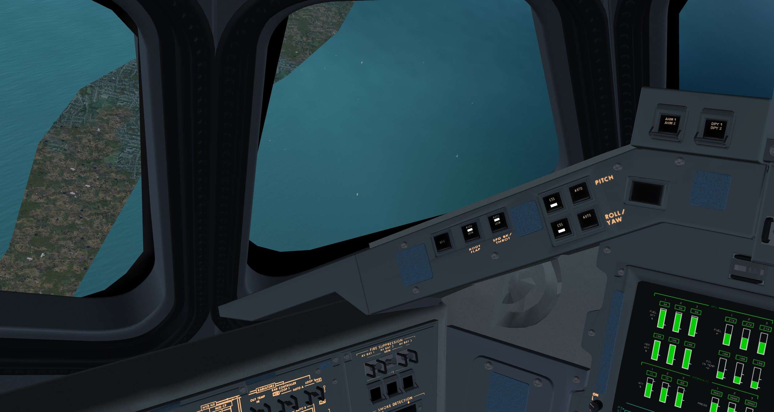
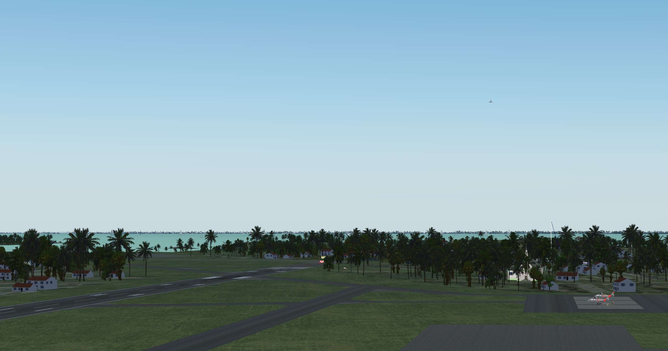
TAEM interface, we are on track for runway 12 in Bermuda.


HySn2C.jpg


Now, another feeling is rising in me. I will have to land that flying brick onto an Emergency Landing Site with a short runway.
What a challenge.
I have been trained during 5 years for that, let's do it


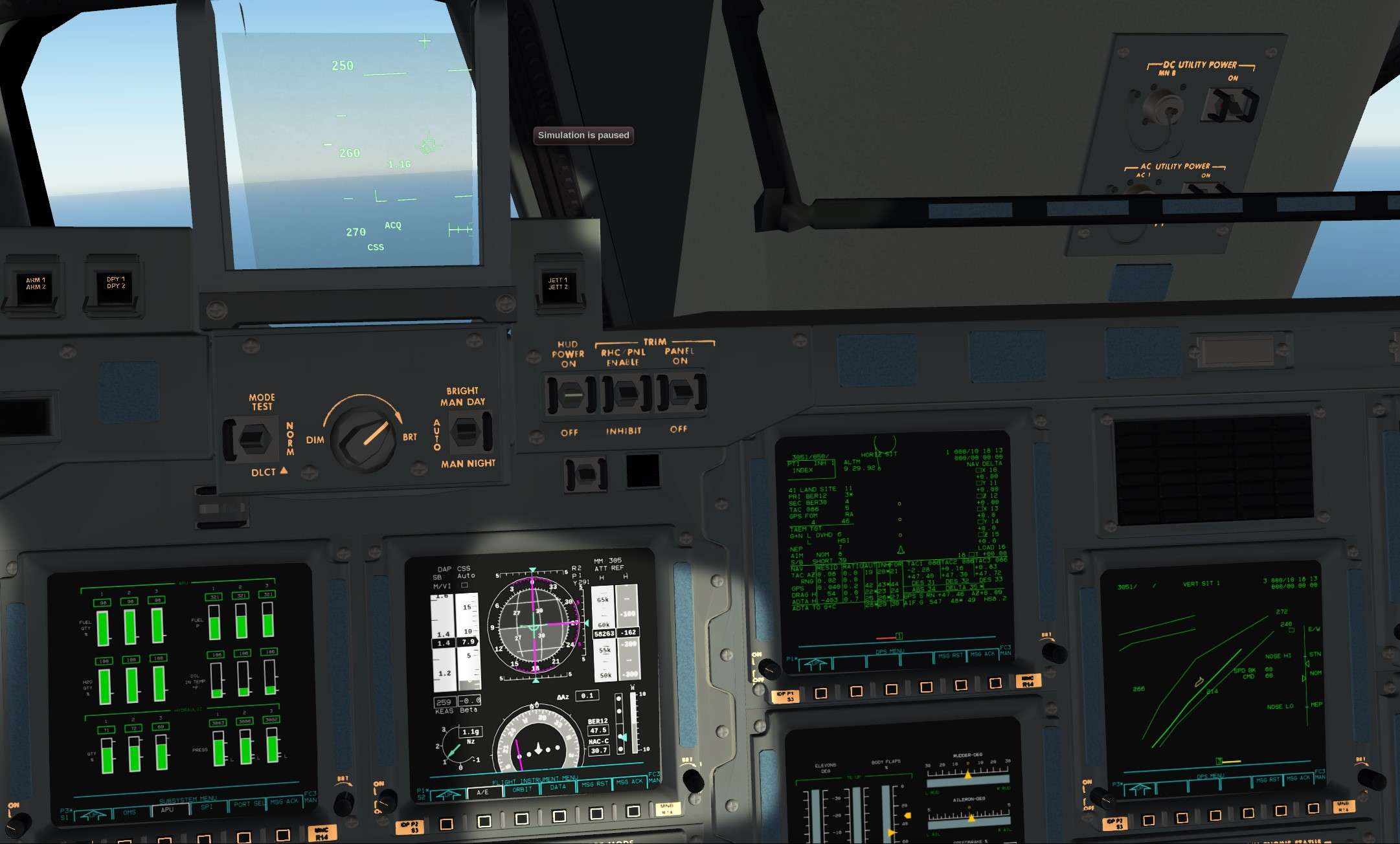
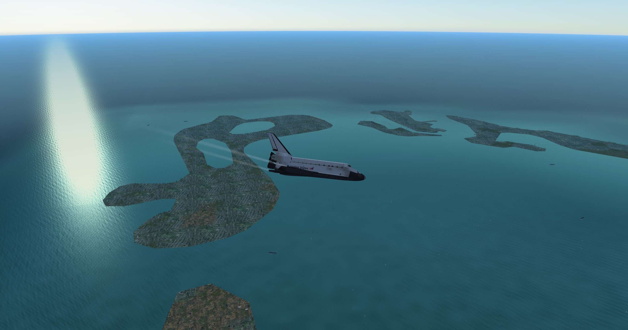
We go subsonic and go full manual CSS, Time for me to shine one last time

Hu4vSR.jpg


Final turn into the HAC, quick glance to the Yacht in that crystal water. Soon maybe we will relax there...

d2Q768.jpg


DDpDtW.jpg


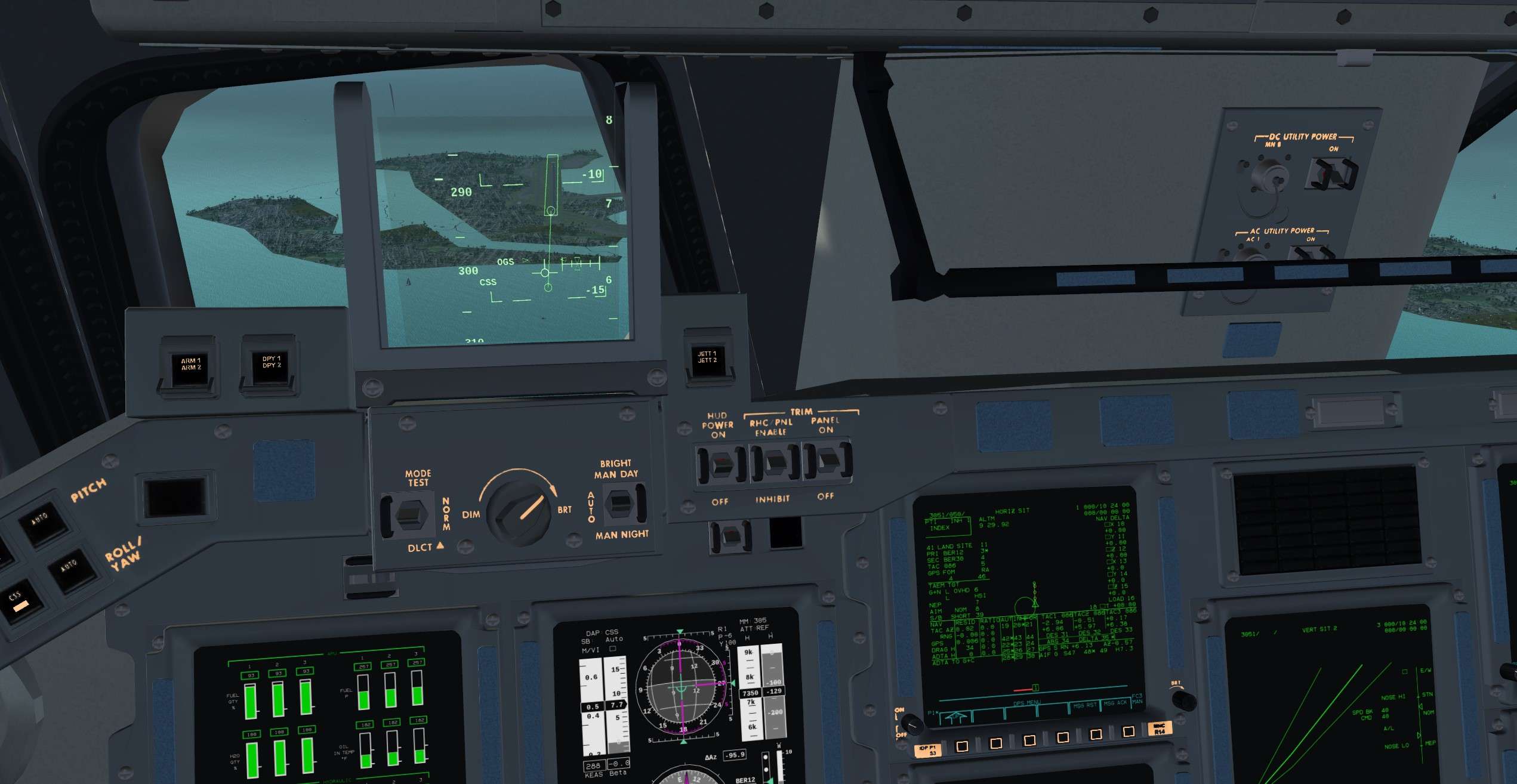
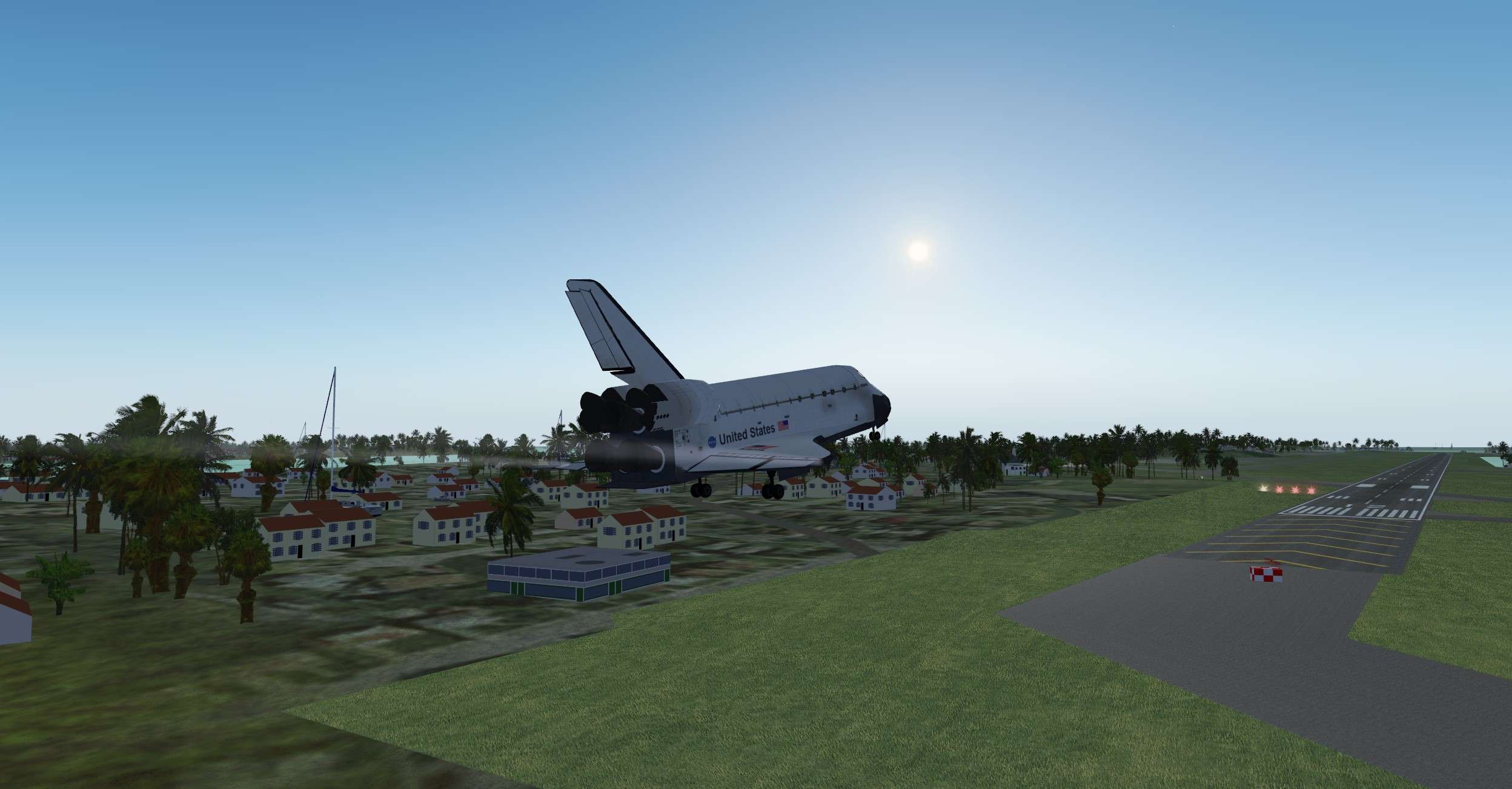
Short final, State vector is good despite the lack of MLS to precisely update it. Almost there

J6d0zS.jpg


ATC guy confirms he got us in sight

kYotQ3.jpg


Here come the final flare, My god, that runway is really short, should I land firmly to assure us a safe stop on the runway?

sU8tdj.jpg


Answer is yes, I pefered to land a bit firm and break the main gears instead of overrun the runway.

dGTx33.jpg


The longest 20 mn of my life, I am now looking to my crew and can feel the relieve in their eyes.
Let's finish the shutdown and secure actions.

Nobody from Nasa is waiting for us there, and we still have very hazardous things in our tanks.

No doubt, I will have a long debrief with the Chief Pilot, but we saved the day and almost a Shuttle.

Time to sleep
 

Thorsten

Active member
Joined
Dec 7, 2013
Messages
785
Reaction score
56
Points
43
I wish we could have the same abort simulation capability here in Orbiter.

It's one of the areas where something born as a flightsim can excel - because you need a good grasp of the aerodynamics in the simulation to get it good if you don't want to cheat (during the Nz hold, the whole aerodynamics changes drastically).

Even so, already having the relevant AP modes (entry and Aerojet) coded, it's no easy task - the whole abort AP logic has by now over 3000 lines of code (not counting the displays and controls).that uses plenty of low level helpers (e.g. I can instance and run a PID controller with integrator windup protection in less than 10 lines).

It's nothing you do on an afternoon :)
 

Urwumpe

Not funny anymore
Addon Developer
Donator
Joined
Feb 6, 2008
Messages
37,616
Reaction score
2,337
Points
203
Location
Wolfsburg
Preferred Pronouns
Sire
I wish we could have the same abort simulation capability here in Orbiter.
Maybe SSU one day...

Might come in SSU, once the DPS low-level stuff is improved, this needs to be done first. But that's off-topic here.
 

Wolf

Donator
Donator
Joined
Feb 10, 2008
Messages
1,091
Reaction score
11
Points
38
Location
Milan
Thanks Wolf

You can do it in SSU, with no AP, but with a good understanding of contigency abort and manual flying, you can achieve great things :)

https://www.orbiter-forum.com/showthread.php?t=38441


Read the above thread and see my comments ;). What I meant is having the capability to simulate aborts and failures the way it is modeled in FG Shuttle.
Maybe Thorsten would like to join the SSU team and increase its manpower?..
SSU guys are working very hard on stuff that clearly has priority and they have also, like everybody, a real life to deal with. I am sure they would welcome other smart skilled coders to join
 

Thorsten

Active member
Joined
Dec 7, 2013
Messages
785
Reaction score
56
Points
43
Maybe Thorsten would like to join the SSU team and increase its manpower?.

Actually I can't - I'm the Linux and OpenSource guy, remember? I acknowledge that SSU is properly OpenSource licensed (and I am occasionally bouncing information or stuff with the SSU team and, should they see any use for my AP codes, they're entirely free to adapt them and I'll throw in explanations for good measure) - but Orbiter is not and won't run under Linux. So there's that.

Having said that - would you come over and do your texturing work for the FG Shuttle? Probably not - and I completely respect that. Generally we all make our choices what we dump our working time into for our own reasons, and the best teams form on their own, without being prodded.

No hard feelings here, but I generally don't think it's a polite thing to ask.

(And I would respectfully note that the things that have priority for me are likely different than what they are for you...)

---------- Post added 06-01-18 at 02:13 PM ---------- Previous post was 05-31-18 at 05:48 PM ----------

Since I wrote the rain splash shader in the first place, it'd be a shame not to use it for the Shuttle - although there's little use case if you fly by the book.

But... it's a simulation :lol:

On the pad, but no lauch today, rain gently tapping on the windows.

shuttle_rain01.jpg


Don't do this unless you're a professional (and even then...) - CAT-I approach to KSC, if MLS doesn't lock on, you're so screwed...

shuttle_rain02.jpg
 

Thorsten

Active member
Joined
Dec 7, 2013
Messages
785
Reaction score
56
Points
43
It's been a while, but we're still working towards a better Shuttle.

* working circuit breakers for several subsystems are being installed, with the plan to improve the handling of electric failures (and of course to get closer to 100% checklist doability)

* another immersive (but otherwise pointless) touch - the dirt on your laptop display which is so annoying when glancing light hits the screen is now also being rendered on the MDUs

display_shader_dust.jpg


(might have to click on the picture to appreciate it, I've over-done it a bit for demonstration...)

* and the next edition of 'The Manual' is nearly ready

Edit:

* and launch guidance has been equipped with the experimental ability to fly a dog-leg and target something outside the 'natural' plane (doesn't work perfectly, but sure is... interesting)
 
Last edited:

Thorsten

Active member
Joined
Dec 7, 2013
Messages
785
Reaction score
56
Points
43
The ubiquitous velcro strips are something that has been bugging us for a while - it's pretty hard to get the visuals right.

Today I realized that I already have the effect I need at my fingertips - it just needs to be adapted to the interior lighting model.

Here's a first experiment:

velcro.jpg


Nice and fuzzy... now it's a lot more velcro-like.

(I wouldn't ever have put the time in to write this from scratch just to get velcro right, but the adaption was just 2 hours work)

(For those who know rendering - it's a fur shader - a geometry shader extrudes a stack of a dozen extra triangles and the fragment shader superimposes a noise-generated blade pattern on it)
 

thammond

New member
Joined
Apr 25, 2008
Messages
90
Reaction score
0
Points
0
Location
Watertown
Nice touch with the screen dust:tiphat:. Any chance to be able to virtually clean it off (with NASA tested and approved screen cleaner of course):).
 
Top