News The Space Shuttle for Flightgear 3.6

Gingin

Member
Joined
Feb 5, 2015
Messages
270
Reaction score
23
Points
18
Location
City of Light
Tried a couple of approaches, very nice work on the trainer.

Some screens of the test, next for me is to master Advanced weather, your TSRA screens are astonishing.

Some landing approach at KTTS at Dawn

12000feet, 6Nm


EyGnEn.png


m47VLL.png


SD6fwW.png


Flare and Gear dropped

pfweEr.png


xwHnOE.png


wWMYWd.png


Touch, Parachute, Roll Out


1OyBhE.png


e1IlFz.png


Verdict, not too bad, better than in Banjul for sure :)

6BbEOi.png


Some nights test, very disorientating


4WAFFg.png


wkSL45.png
 
Last edited:

Thorsten

Active member
Joined
Dec 7, 2013
Messages
785
Reaction score
56
Points
43
In an effort to make more landing sites available, I've now added Wilmington, Myrtle Beach, Atlantic City and Gander - together with Halifax this should give some ECAL options.

Also, for a very scenic spot, try Honolulu Intl. Airport.:)
 

Gingin

Member
Joined
Feb 5, 2015
Messages
270
Reaction score
23
Points
18
Location
City of Light
Ah very nice !!
I will try 2 eo green for sure so :)

Ok, lets go for Hawaï, I think it's gonna be hard on the config .

Do you think your approach trainer would work if we start at TAEM interface?
It's a really great addition, I tried as you space cowboys TSRA approach, no joy. :)
 

Thorsten

Active member
Joined
Dec 7, 2013
Messages
785
Reaction score
56
Points
43
Do you think your approach trainer would work if we start at TAEM interface?

The evaluation functionality yes, the reset probably no - weather for sure and potentially also terrain don't like teleportation across large distances, this will trigger all sorts of quirks.
 

goForTLI

Donator
Donator
Joined
Aug 25, 2017
Messages
44
Reaction score
16
Points
23
Location
MG-Alvinopolis
It seems to be very good. I have never tested this complement of the flight gear simulator. So I would like to know if there are historical scenarios like sts 1.

thank you so much!!!

:thumbup:
 

Thorsten

Active member
Joined
Dec 7, 2013
Messages
785
Reaction score
56
Points
43
So I would like to know if there are historical scenarios like sts 1.

FG isn't really a mission or scenario simulation - it basically simulates a Shuttle and you decide what you want to do with it. You can follow a historic mission plan - or you can do goofy things (GinGin apparently had fun of late trying to see whether he could land the Shuttle in Paro Airport (Bhutan) in a Himalayan valley - which is a tricky approach even with an airliner).

You have the limitation that what's modeled is Atlantis in a late config (e.g. with glass cockpit and as single string GPS vehicle) - that's rather different from the STS-1 experience. And there's very few payloads implemented.

So it's really up to you to define what the mission is - the simulation won't do that for you.

***

The approach trainer was worth the effort, it's so much fun trying all the different environment conditions and see how they affect the approach experience.

On IGS preparing to touch down at snowy Keflavik, Iceland - you can see some activity of the airbase in the background...

shuttle_approaches16.jpg


Another approach into Keflavik - with some of my favourite clouds. I've always liked being between two cloud layers.

shuttle_approaches17.jpg


Some drift ice on the water, the coast of Iceland in view...

shuttle_approaches18.jpg


... it's the kind of natural beauty which makes it hard to focus on the HUD...

shuttle_approaches19.jpg


I always use such scenes to illustrate that haze is anything but simple - there's a lot of hue variation in clouds and haze underneath based on just how light reaches them. It's a few hundred lines of code per pixel to compute it.:lol:

(On a personal note - wanting to fly my simulated craft between two cloud layers because I've always loved seeing that for real when traveling was one of the things that really got me started in coding weather simulation.)
 

Gingin

Member
Joined
Feb 5, 2015
Messages
270
Reaction score
23
Points
18
Location
City of Light
Indeed, approach trainer is tons of fun, head cross tail wind, CB or fog, wind shear.
Great stuff, how many hours did you spend on it?

@goForTli: you can do a lot with this sim, working on différents parts separately like entry or approach or ISS rdv. Then you can do a full mission when you feel ready.
A lot of possibilities for non normal situations also.
It's both educational and fun sim to play.

Speaking of goofy challenges, some screens to highlight that :)


Q66oV8.png


5e1mUW.png


Or you can fight against nature forces


3kXmnv.png


Poor visibility and microburst are really a madness

AkiXrp.png
 

Thorsten

Active member
Joined
Dec 7, 2013
Messages
785
Reaction score
56
Points
43
The new ECAL map - useful for situational awareness during contingency aborts if you hope to reach a landing site.

ecal_map.jpg
 

Thorsten

Active member
Joined
Dec 7, 2013
Messages
785
Reaction score
56
Points
43
Teaching the AP to fly a 3EO GREEN abort.

shuttle_3eo.jpg


Let's say the AP is doing a great job, but black zones are damn real. So far I've not seen an attempt that did not result in a breakup of the Shuttle.

This one was at Mach 10, and the scenario is excessive EAS during Nz hold, resulting in LOC and breakup.

One problem I've not seen discussed anywhere is that if you have a simultaneous three engine out, there's really not enough time to get rid of OMS propellant before the Shuttle hits the atmosphere - not to mention the MPS dump. So when you could need any shred of control there is, you're tail-heavy with a bad CoG. The whole thing is an unconditionally nasty piece of work.
 

Gingin

Member
Joined
Feb 5, 2015
Messages
270
Reaction score
23
Points
18
Location
City of Light
3EO , great :)


I was tested lately different intact aborts, and I wanted to highlight a bit more the Return To Launch Site to KSC.
You can see how far in non normal ops we can go in FG.
It is one of the most impressive I find.
To fly outbound leg at Mach 7 then invert the speed to come back at Mach 7 towards Florida. It gives vertigo considering how tight the margin is to meet all the guidance and navigation requirements to end up gliding back towards KSC.


One very important reading is the RTLS part in the Intact Ascent Aborts Workbook: https://www.nasa.gov/centers/johnson/pdf/383447main_intact_ascent_aborts_workbook_21002.pdf
Everything happens fast in a RTLS, so it's nice to have in the head all the sequence of what will happen. It helps to monitor the AP and take over manually in case of divergence from the nominal track.

Moreover, the work on the RTLS guidance OPS6 , closed loop AP (constantly re evaluating how well it is doing and makes corrections to account for any errors), is astonishing, and very precise if the abort is not declared after the Negative Return Border ( 4 mn into the flight/ Vi around 8 kft/s) in the sim.


Here a sum up of differents boundaries, which are almost the same for every missions, plus or minus a delta Vi depending of the Orbit Inclination Targeted.

6tUf7G.png


One thing with abort is that no abort will be declared until 2:30 mn in the mission.
So even if an engine fails during First Stage Ascent ( before SRB Sep), and RTLS is selected, it will not begin the guidance before 2:30mn.
That was to let the time to the Orbiter to stabilize after SRB Sep, and to damp any transient states left from SRB guidance.

Latest time to declare a RTLS is at 4:00mn, after the downrange and speed are too high, and TAL would be selected.
Usually, for a failure other than an engine, decision to take RTLS or TAL abort was delayed until 3:40 mn to let the time to MCC to evaluate the gravity of the failure, and choose the best abort to deal with it.


I) From Lift-Off to PPA


Starting on the pad, early morning

hqq3SN.jpg


Xx47PG.jpg


Checklists done, Final Countdown and Main Engine Ignition
The Shuttle wakes up all Florida

tR8VRw.jpg


Tower cleared, farewell Atlantis, and safe journey

uGyEE5.jpg


Failure on the center engine implemented after 2:30 mn

YinVek.jpg


Abort initiated by the Commander,

4z0CyX.jpg


5GGT1d.jpg


Many things will happen, Real Checklists in game are available ( Cue Cards), with actions for both Commander and Pilot. Sometimes, a pause in the game might help when it is becoming to dynamic.


First, let's select Max throttle to allow the engines to have access to more power if required
Spec 51 PRO and Item 4 EXE

ztKwg1.jpg


Let's talk about guidance convergence. It will indicate how well is performing the AP, and should decrease close to zero to show that the guidance is nominal and thrustworthy.
Just check the tendency first, if it's decreasing, it's good sign, if not, take manual control

075h6e.jpg


Below unconverged guidance table, you will find some hints on pitch to take during outbound and inbound legs, as well as the % of propellant when to do the turn around towards KSC
It's usefull for Manual RTLS, but also to monitor what the AP is doing.
Here, failure at 2:30mn, so outbound pitch around 42° and PitchAround when Porpellant ramining is around 50 %

xMeH4R.jpg


Next step, propellant dump in OMS tanks.
Aim here is to advance Center Of gravity to avoid Loss Of Control(LOC) during entry.
Have a look to the crossfeed valves of both RCS and OMS systems, closed prior to the dump

uJgO2z.jpg


Automatic reconfiguration will happen during time critical phases, like abort.
OMS tanks will feed RCS thrusters and those will simuteanously fire to dump propellant.

SPEC51 PRO to call the Override Page
Item 6 EXE Item 7 EXE to iniate the dump.
Time to Go of 132 seconds until depletion of OMS Tanks

nc2zt9.jpg


Have a look again to RCS and OMS panel
CrossFeed Valves are now open, and RCS Isolation Tank Valves are closed. RCS are fed by OMS tanks only to avoid back pressure into RCS tanks, brillant piece of mechanics.

XZTLWE.jpg


Around 7kft/s of inertial speed, we are approaching 50 pourcent of propellant ramaining.
It's time for the PPA, Powered Pitch Around, where the Shuttle Pitches Around towards KSC


II)PPA to PPD


Time for PPA, Guidance has fully converged, and remaining propellant around 50 % like planified, perfect.

UQoIWx.jpg


Back to the Cap

B89rgb.jpg


Dump finished, red alert announcing OMS tank pressure Low
We can check deeper on the Sys 2 page, Low pressure in Helium OMS tanks and Low quantites( below 5 %)

ek0AfD.jpg


A very impressive situation now.
We are inverting our Velocity Vector, Speed relative to Earth is null.
If we loose other engines now, we fall back straight to the sea. One of the most tricky situations during a RTLS

zQsUUI.jpg


Stationnary position for a brief moment :)

9m09yA.jpg


Next crucial step is the PPD, Pitch Powered Down.
Very important manoeuver preceding MECO
Thrust will be gradually decreased and Orbiter will pitch down to an angle of attack of -2° for ET separation. And all that without degrading guidance too much

Approaching the PPD

yWjuR7.jpg


And PPD followed by MECO, note the angle of attack

8XKm12.jpg


Check that the ET is well separated, if not do it manually with Manual ET Sep switches

eB8S51.jpg


Then check that GPC transitionned to the next guidance Phase, OPS 602 Glide Return To Launch ( GRTLS)

yUsfgj.jpg
 

Gingin

Member
Joined
Feb 5, 2015
Messages
270
Reaction score
23
Points
18
Location
City of Light
And also, have a look to confirm that Pitch Roll/Yaw Speedbrake and Body flap are in Auto mode

hAzEYe.jpg


III)GRTLS

Another tricky phase.
MECO occured, we are falling back with a high Vertical Speed into atmosphere, which we gonna it hard.
Aim here is to not break the orbiter by over G's or EAS exceedance.
Normal limits are G=2.5 G and EAS=330 kt, which can be extended to G=4.1 and EAS=470kt for Contigency aborts. These last ones are hard boundaries which will probably break the Orbiter or lead to LOC.


Time critical situation before entry, so ET doors and propellant dump are initiated automatically to move forward Center of Gravity

oc9yHY.jpg


Alpha recovery phase now.
Orbiter will hold a 50° angle of attack attitude until reaching 2 G

MAXWmR.jpg


Nz hold phase. Depending of the Vertical Speed, Guidance calculates a number of G ( Nz) to maintain to avoid structural damages.
Here it's around 2.8. So when reaching Nz=2.8 G , Alpha will be decreased by a pitch down manoeuver to maintain Nz constant.
Nz hold is a phase where boundary between G and EAS exceedance is very tight.
Manual way to calculate it: When Nz=1G, note the VS ( it was 2000ft/sec) Nz to hold = Vs at 1G/1000 + 0.65

So, Nz= 2000/1000 + 0.65= 2.65 G ( quite close to the computed one)

iSMBwa.jpg


Some visuals, no plasma, a bit of glowing tiles

Mbjp1K.jpg


Then comes Alpha transition Phase
When Vertical Speed is above -300 ft/sec and increasing, Alpha will vary accordingly to the Mach
We can see on the picture some phugoid oscillations, positive vertical accel and speed, up and down :)
Also the EAS now decreasing, quite high. We could have take Pitch in CSS to allow a bit more G during Nz Phase ( less pitch down) to avoid speed to increase to much. Very tight border here between pushing and pulling on the stick.
We didn't break any hard boundaries, so far, so good.

I9isOq.jpg


Rl33ce.jpg


Gliding back towards KSC now, back on a nominal entry profile.


On Spec50 Horizontal Display, we incorporate TACAN into Kalmann Filters to affinate the State Vector (SV), Ratio is under one and Residual low, SV is looking good.

qTlHPi.jpg


M=5, probes are deployed

Rt5GAm.jpg


Next Guidance transition, OPS 603 ( Vert Sit 1 and 2)
We check also on Spec 51 that the Probe Data ( ADTA) are correct, cross checked with PFD value coming for now from IMU
If good, Altitude coming from probes is incorporated in Nav Software by Item 25, and Mach,Altitude, Alpha willl feed the Guidance Software and show up on PFD by pressing item 28

9niRWH.jpg


T6RzwV.jpg


We can ask to MMC how is our SV by a Delta State Update, quite Ok now, ( some small divergence on X,Y, Z axis with reality)

VE9YbY.jpg


Approaching Mach2.7, HUD power On

792Ag8.jpg


Around 85000 feet, MLS ( Kind of ILS for precision Landing) channels are selected correctly, number 8 for runway 15 in KSC ( 3 redundant channels)

vikdb2.jpg
 

Gingin

Member
Joined
Feb 5, 2015
Messages
270
Reaction score
23
Points
18
Location
City of Light
Approaching the HAC

j1xSg8.jpg


And it is now time to take manual control by pressing CSS for Pitch and Roll/Yaw channels
After 20 mn of Hyper Sonic Flight, Atlantis is falling below Sound Barrier again

eFBswc.jpg


Overhead the Runway

nLTo4g.jpg


15b7QQ.jpg


Entering the HAC for a full 270° right

0pMR3S.jpg


Last turn

wMSaXi.jpg


On final, below 15000 feet, MLS is automatically activated ( yellow MLS) and TACAN data are not feeding anymore the navigation filter
MLS is way more precise than TACAN, updating the SV in a better way.
Impressive to see how close to reality those things have been implemented

rzBGLj.jpg


Still a bit of error with SV,but quite ok.
We could have make a GPS Sv update to have a perfect SV, but it's precise enough for a safe landing...I hope :)

rzhmqP.jpg


Then at 2000 feet RA, Pre flare and HUD Declutter to follow the guidance
300 feet RA Gear down and Final Flare

wMEhQs.jpg


60 kts, Drag chute dropped and Wheels stop
Welcome back, Atlantis

8OR1ln.jpg


Small Highlight on Freon Temperature reaching 70 °

xt4Z5T.jpg


NH3 boilers can be activated below 120000 feet when FES system is becoming useless to cool Freon Loop, no time for Freon Cold Soaked in Radiators during Abort :)

VLcyHq.jpg


Hope yo enjoyed it.
I am really happy with how the guidance works for RTLS
 

Wolf

Donator
Donator
Joined
Feb 10, 2008
Messages
1,091
Reaction score
11
Points
38
Location
Milan
Very nice Gingin! It is amazing what FG Shuttle can do :speakcool:
 

Thorsten

Active member
Joined
Dec 7, 2013
Messages
785
Reaction score
56
Points
43
Some details on how to interact with the DPS - I'm making some progress in memory configuration management (this is implemented optionally because it's pretty easy to make a mistake - if the simplified option is chosen, this will 'just work' when an OPS transition is made and SM and BFS will just be there).

So, here we go, DPS config to OPS 2. It's not all completely like in reality yet, but fairly close.

We're going to make heavy use of SPEC 6 (to see what the current config is) and SPEC 0 (to make any changes).

memory_reconf01.jpg


We are in OPS 1, MM 106, post-insertion. The first step is to create a freeze-dried copy of OPS 2 software in GPC 3 in case of mass memory failure later. To do that, we first take GPC 3 out of the redundant set.

Currently, GPC 3 commands string 3, so we change that. On SPEC 0, we select config G1 via
ITEM 1+1 EXEC
and then
ITEM 14 + 2 EXEC
to hand string 3 to GPC 2. To apply this, we need to recall current major mode via
OPS 106 PRO

The reward - the string got transferred as seen on SPEC 6.

memory_reconf02.jpg


Next we take GPC 3 out of the redundant set my moding it to HALT and then back to RUN. GPC 3 (currently commanding IDP 3) comes back up in OPS 0.

memory_reconf03.jpg


The devil is in the detail - while we have OPS 0 on the left (i.e. the GPC is in root mode and not computing GNC), on the right the same page is SPEC 0 of OPS 1 MM 106 (i.e. the GPC is doing GNC and presenting a utility page).

We proceed to directly load G2 on GPC 3 by typing into the left display

ITEM 46 + 3 EXEC
ITEM 45 + 2 EXEC
ITEM 47 EXEC

This loads the software into memory, but doesn't actually run it yet (we'd need to do the OPS transition to do that) - so GPC 3 can now show a different memory config.

memory_reconf04.jpg


Since the GPC is to be freeze-dried, we mode the GPC to HALT and assign IDP 3 to GPC 2 via

GPC/CRT 23 EXEC

to get rid of the polling errror. Next we start to bring up SPEC 0 again

memory_reconf05.jpg


and edit G2 via

ITEM 1 + 2 EXEC

and distribute all strings and buses equally among GPC 1 and 2 - which are (as listed under items 2-6) the only GPCs which are to participate in the transition.

OPS 201 PRO now rewards us with this:

memory_reconf06.jpg


Note how the command kicked GPC 4 out of the redundant set since it was running GNC, but not targeted to receive G2 software. We now want to load SM software there.

The first step is to let it command IDP 3 via

GPC/CRT 43 EXEC

then we get access to its OPS 0 page. Here we select the S2 config to edit via

ITEM 1 + 4

and review bus assignments.

memory_reconf07.jpg


Once done, the major function switch for IDP 3 needs to go into SM position (this will tell the system software to load SM next), then we type

OPS 201 PRO

and are rewarded with the antenna management display coming up.

memory_reconf08.jpg


Last step is to secure and freeze-dry BFS, so we bring up BFS on IDP 1

memory_reconf09.jpg


(this comes up in the wrong display since I haven't done the BFS root display yet...) - we take it down by

OPS 000 PRO

and then mode GPC 5 also to HALT - and here we are - two GPCs sent to sleep, two running GNC, one running SM, ready for orbital ops.

memory_reconf10.jpg


Needless to say, the whole thing isn't for the faint of heart, since it requires a good understanding of what all the commands and switches do - GPC/CRT is used frequently, and understanding what commands what at the moment is a must.

Yet, this is pretty much how the original procedure works. Makes you wonder how the Shuttle never had a serious problem because someone messed up interacting with the DPS. As far as interfaces go, that thing is a nightmare...
 
Last edited:

Gingin

Member
Joined
Feb 5, 2015
Messages
270
Reaction score
23
Points
18
Location
City of Light
Impressive work

I tested in depth the DPS system, really impressive.

I made some screens of the procedure during Post insertion of how the transition from OPS 1 to OPS 2 and GPC re configuration was done following real Checks.
I will add it on the Wiki for Post Insertion Tuto

A good introduction book for those who want to appreciate the work made on DPS

Nasa Workbook DPS Overview
https://www.google.fr/url?sa=t&rct=...ttach=143306&usg=AOvVaw10GSCKIigUK4q3hKjETmyA


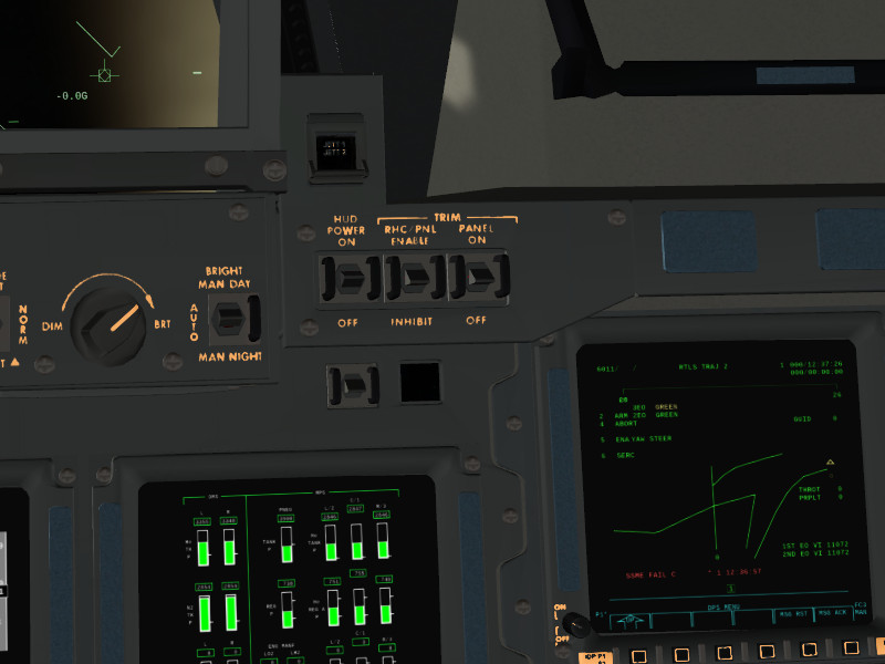
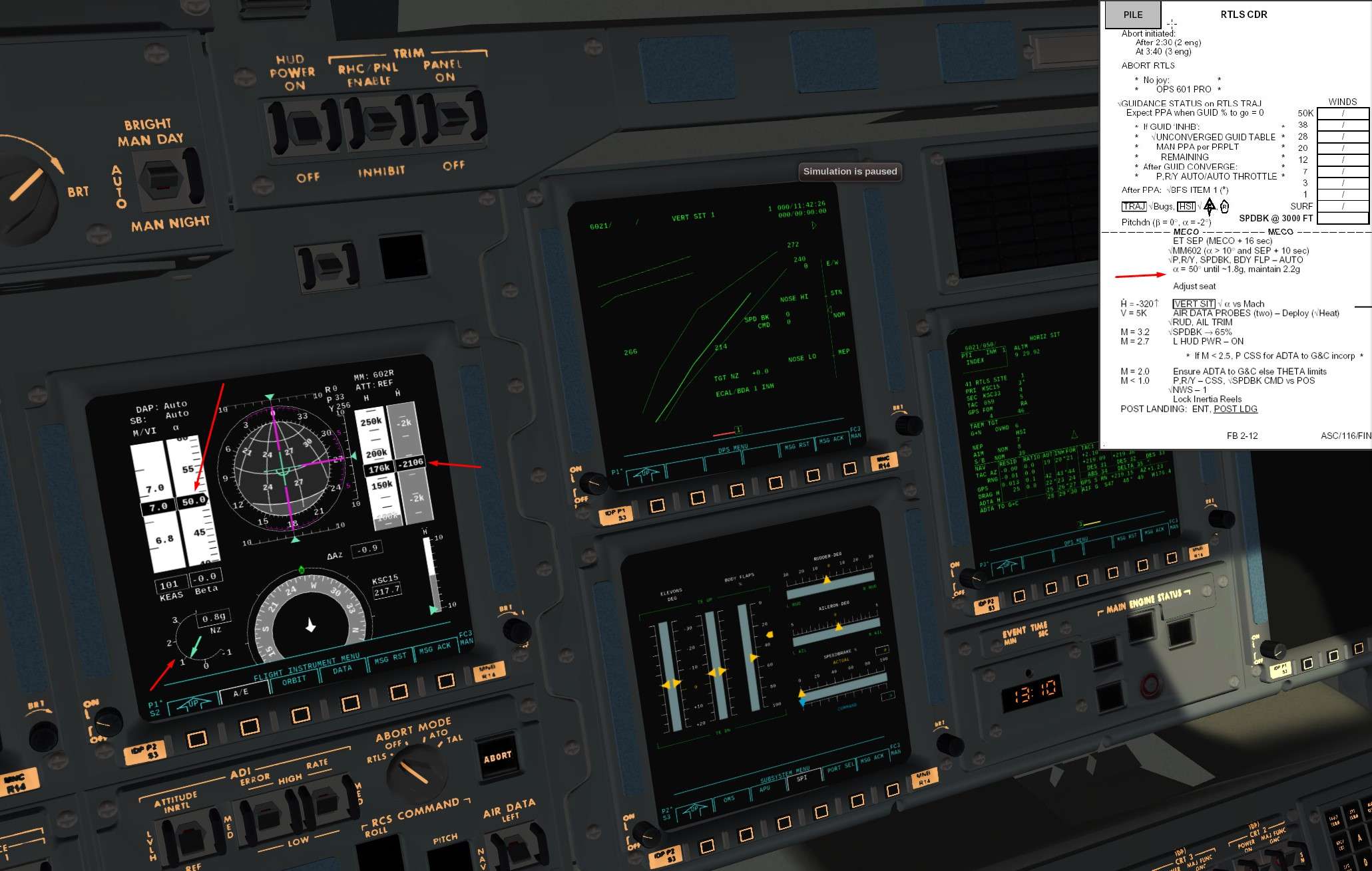
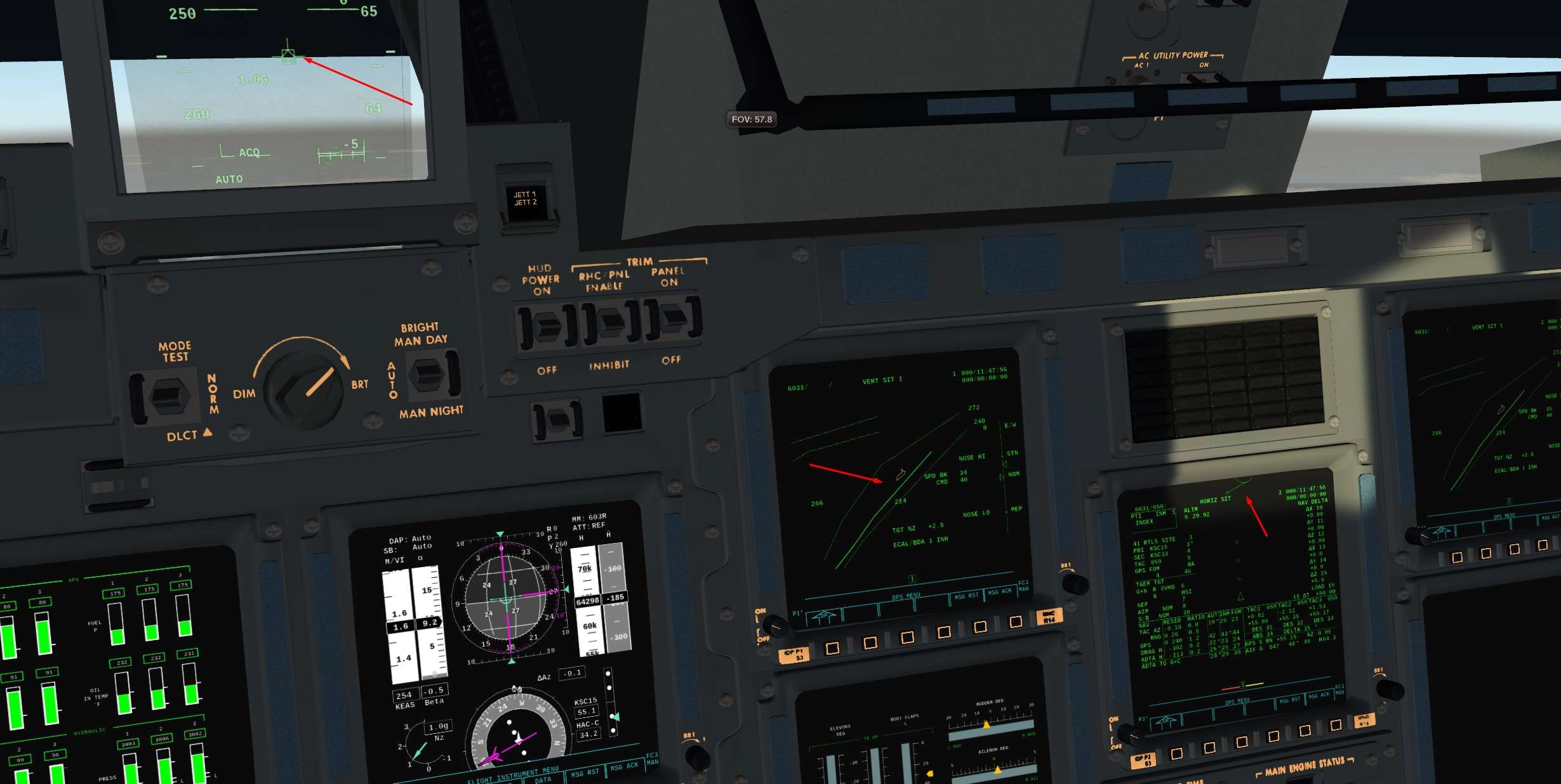
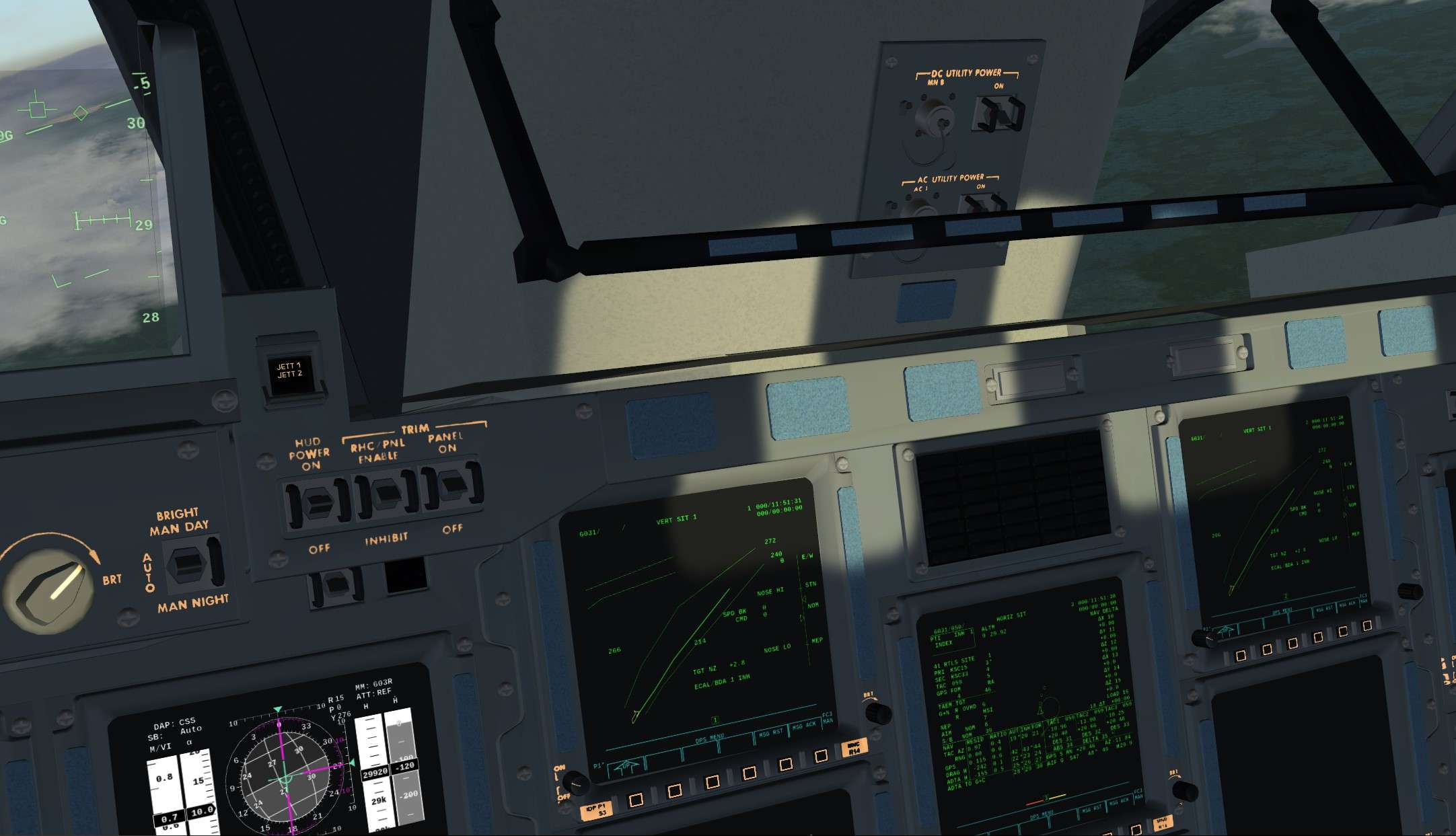
We are in Orbit, OMS burn completed, Cockpit reconfigurated, next step Post Insertion Items

It begins with GPC re configuration and OPS 2 transition
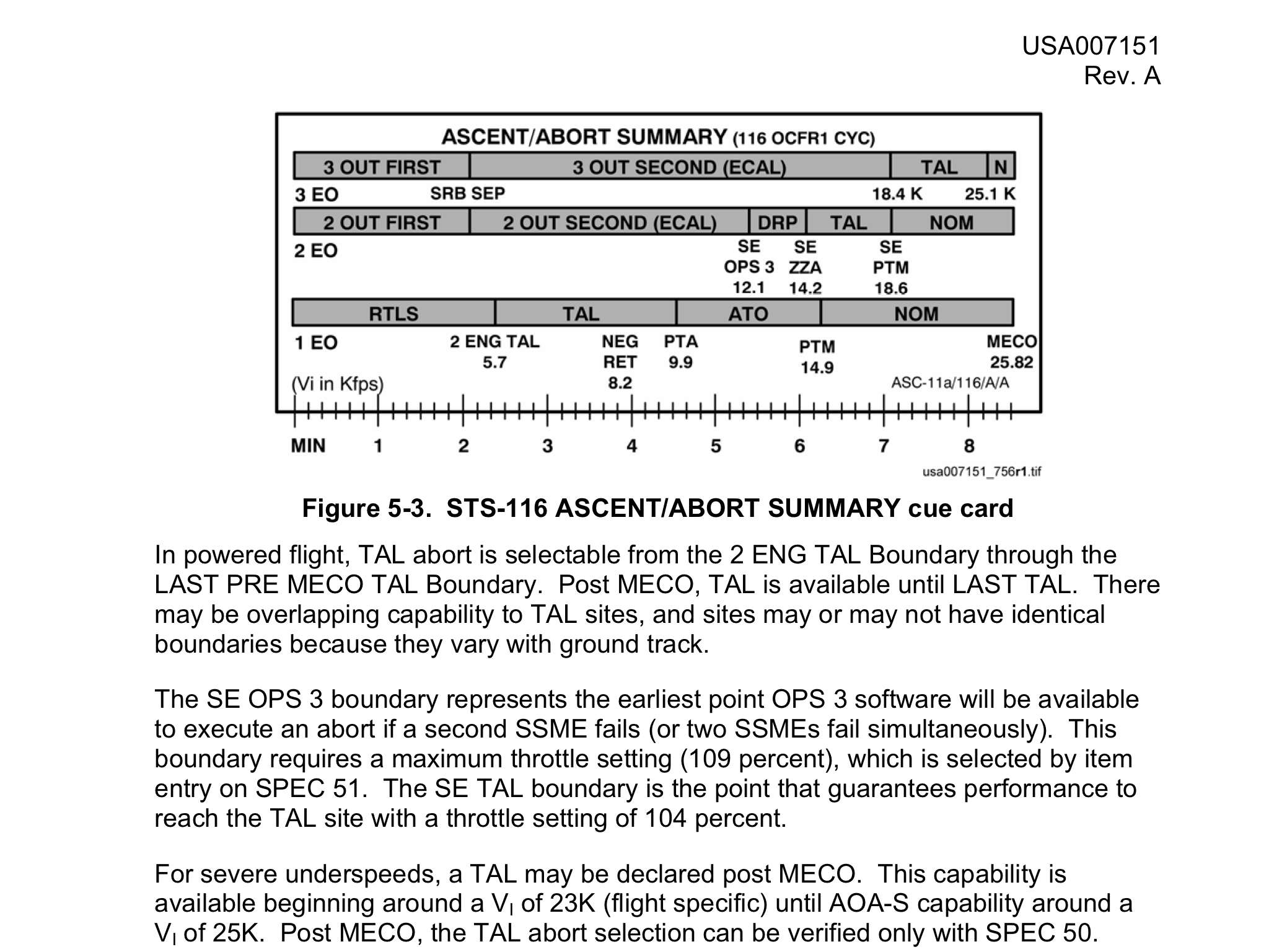
Here are a resume of what we want to achieve


GPC 1 and 2 will contain OPS 2 Guidance, Navigation and Control software (GNC)
GPC 3 will be put in Halt mode ( sleep). He will be freeze dried, which means that before going to sleep, a copy of the OPS 2 software will be loaded into the GPC in case of major failure of the others. Very deep level of redundancy here.
GPC 4 will receive the System Management ( SM) OPS 2 software and will be switch in Terminate mode ( it will not communicate on Flight Critical buses anymore unlike GPC 1 and 2).
GPC 5 that contains BFS software will be put in Halt mode, as no orbit software is contained in Back Up Software and Computer.


We want first to Freeze dried the GPC 3.To do so, we need to be in OPS 0 ( System Application only)
Problem is: It is still in the common set, and if we switch to OPS 0 in GPC3, the GPC 1,2 and 4 will be moved to OPS 0 also
So we need to switch off the communications between GPC 3 and the differents buses linked to him ( Flight criticals -FF-, and the one from central IDP/CRT )


For that, 
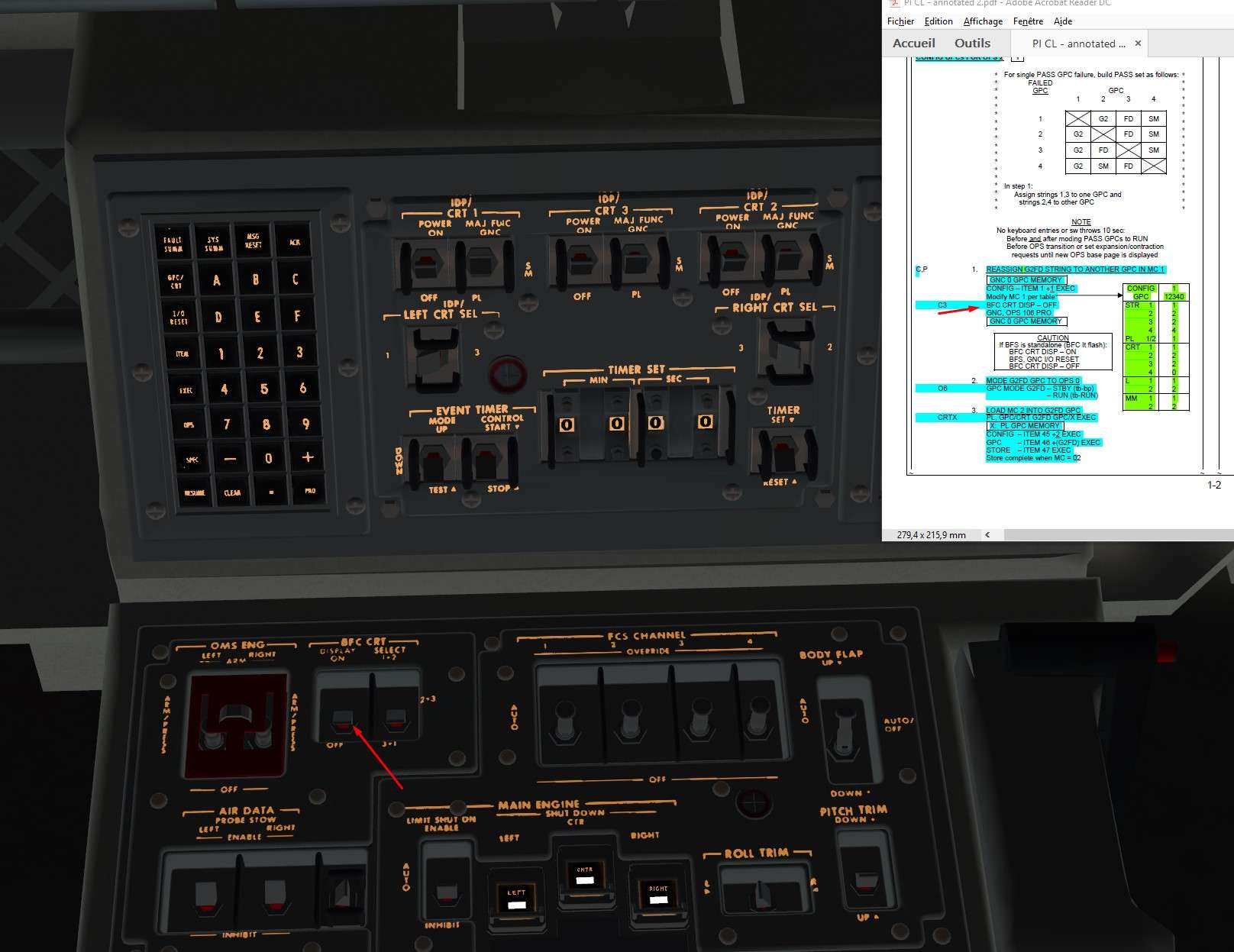
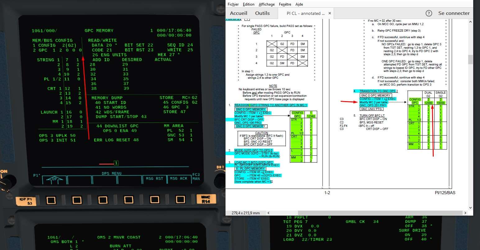
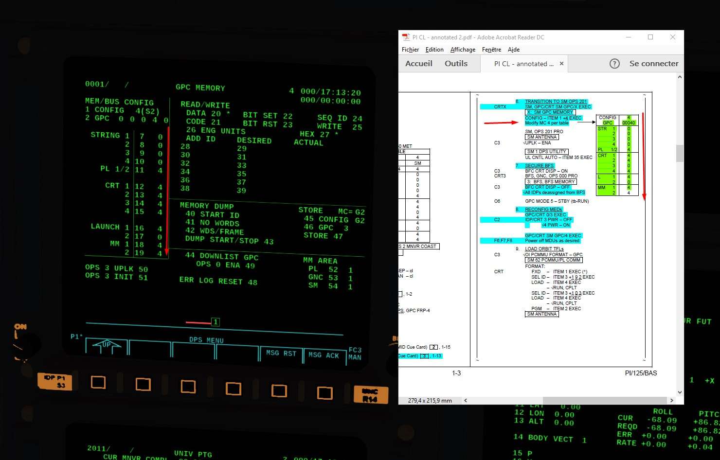
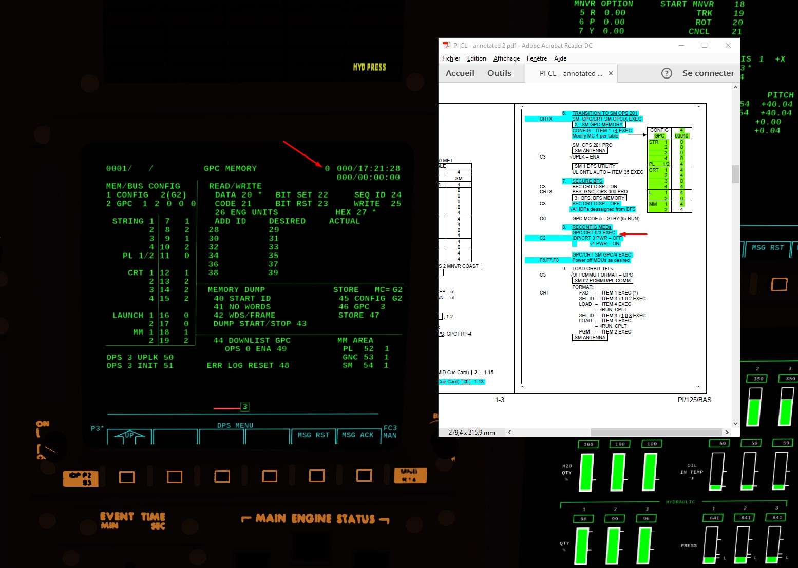
SPEC 0 PRO to acceed to the GPC Memory re configuration screen

h2o5Ga.jpg


Then, we reconfigure the OPS 1 Memory configuration (MC G1) to have the GPC 3 out of the loop

5x1nvp.jpg


We switch of the Back Up Flight Computer (BFC) which was displayed on CRT 3

732w25.jpg


Now, time to see the changes made to the MC1.
Every time we change something in the Nominal Bus Assignement Table (NBAT) through Spec 0, we need to do an OPS Transition or an OPS recall to see the changes applied (Which can be seen in SPEC 6 PRO)

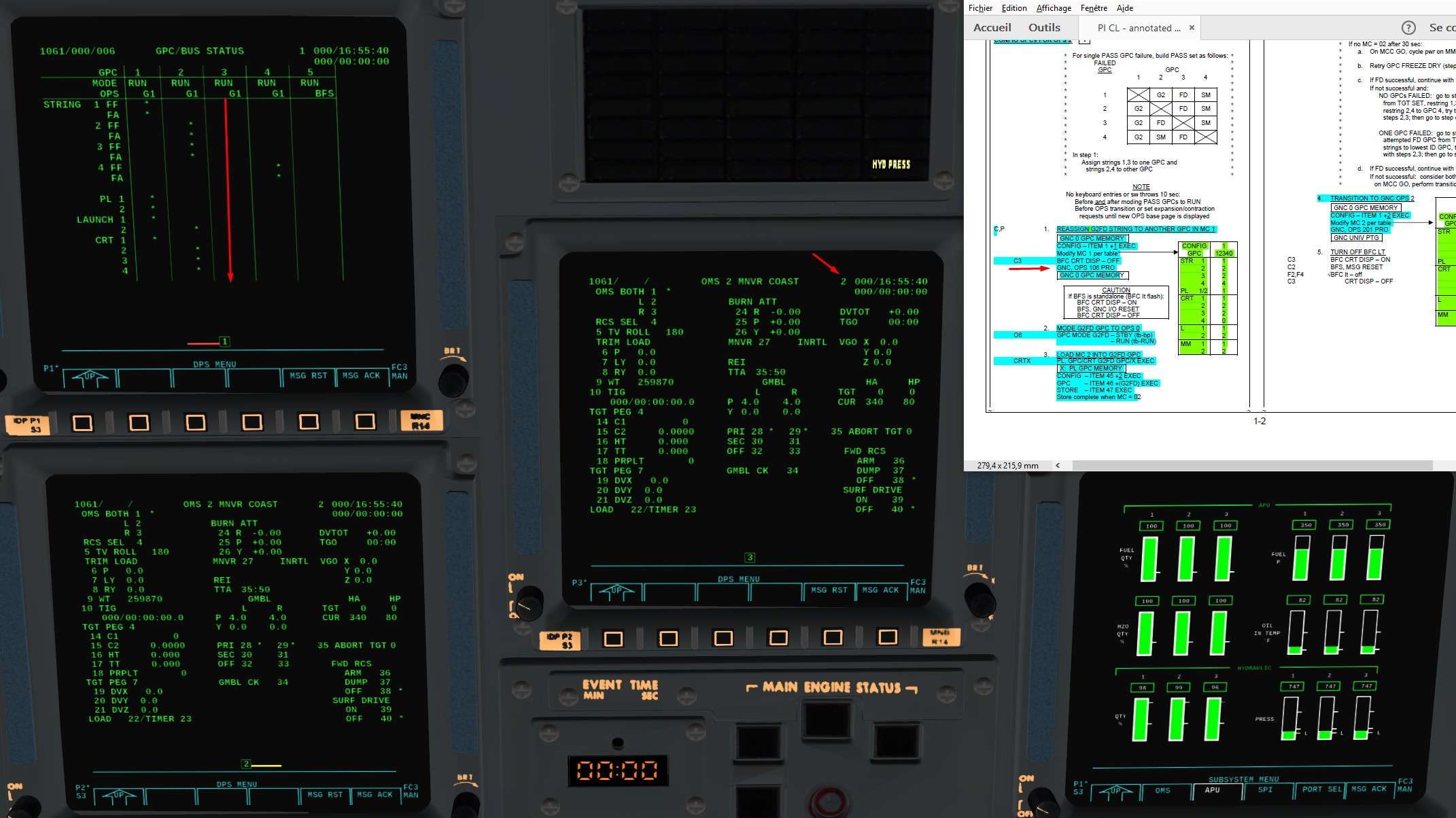
We are in OPS 106, let's do an OPS recall which consist in calling back the same OPS than where we are
So OPS 106 PRO
We can see the changes, GPC 3 is not emitting on any buses, good job

59E6qR.jpg


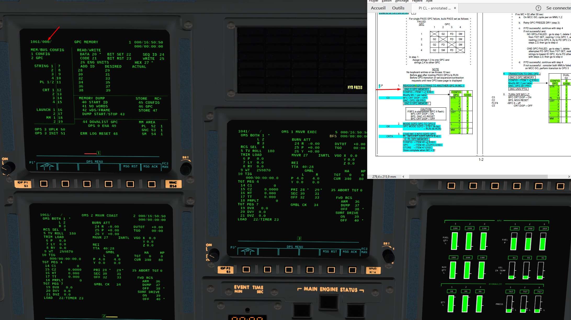
So we can now proceed to the freeze dried.
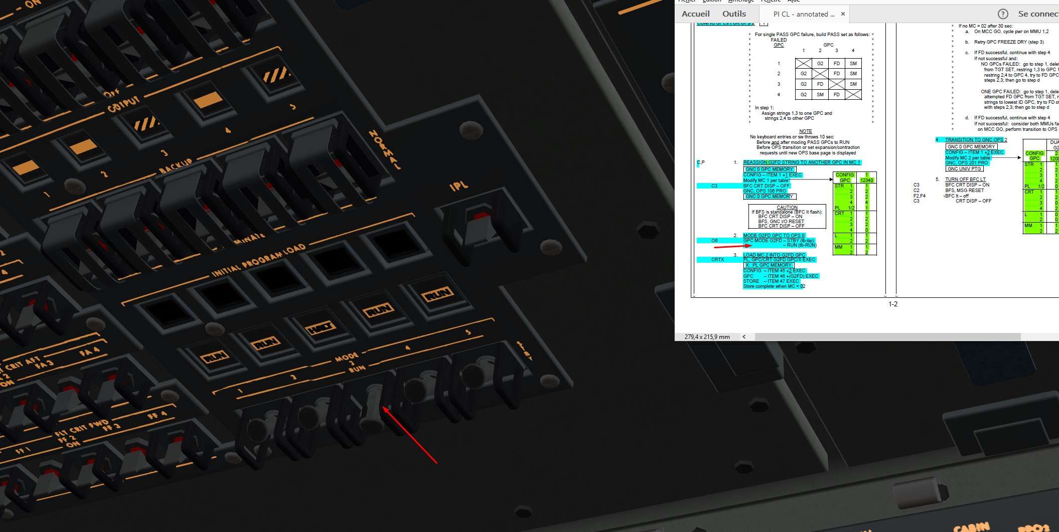
In the checks, the GPC to be freeze dried is written like that G2FD By convention, it was always the number 3. But it can be an other one in case of failure.

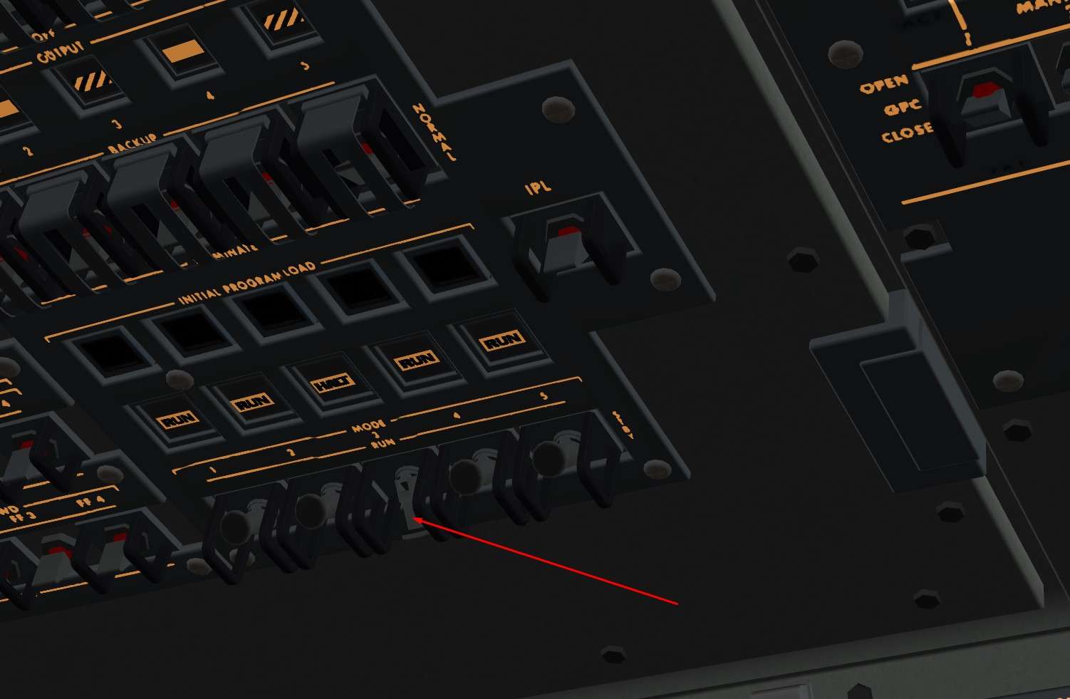
To put it in OPS 0, we switch to Halt (stby in the checks) then back to Run

4IF67c.jpg


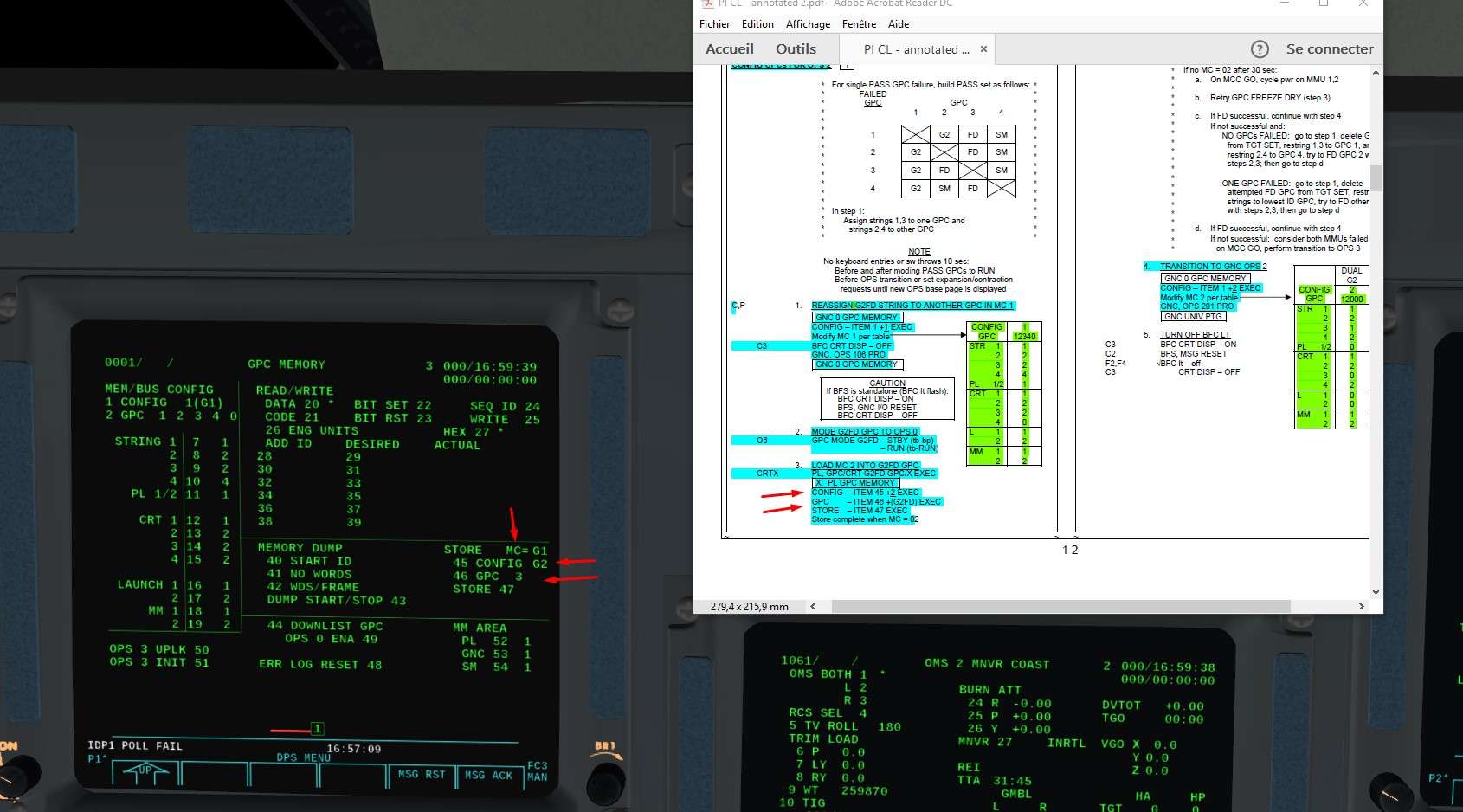
We want to display the GPC 3 somewhere (no CRT is polling it anymore), let's say on CRT 1
For that, magic button is GPC/CRT key.
GPC/CRT 31 EXEC will display the GPC 3 on CRT 1 with OPS0 program

uJGZhQ.jpg


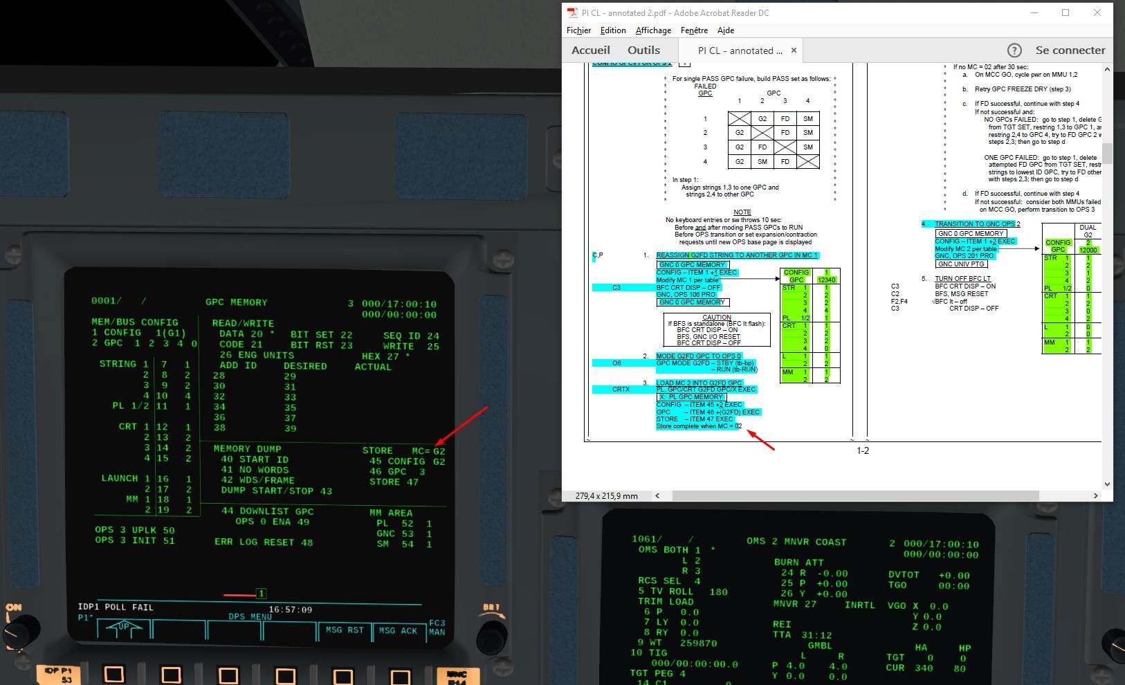
We will load OPS 2 program (MC2) into it now
ITEM 45+2 EXEC
ITEM46+3 EXEC

en5rDy.jpg


And to store it, ITEM 47 EXEC MC=G2 will appear once stored

eB2JFJ.jpg


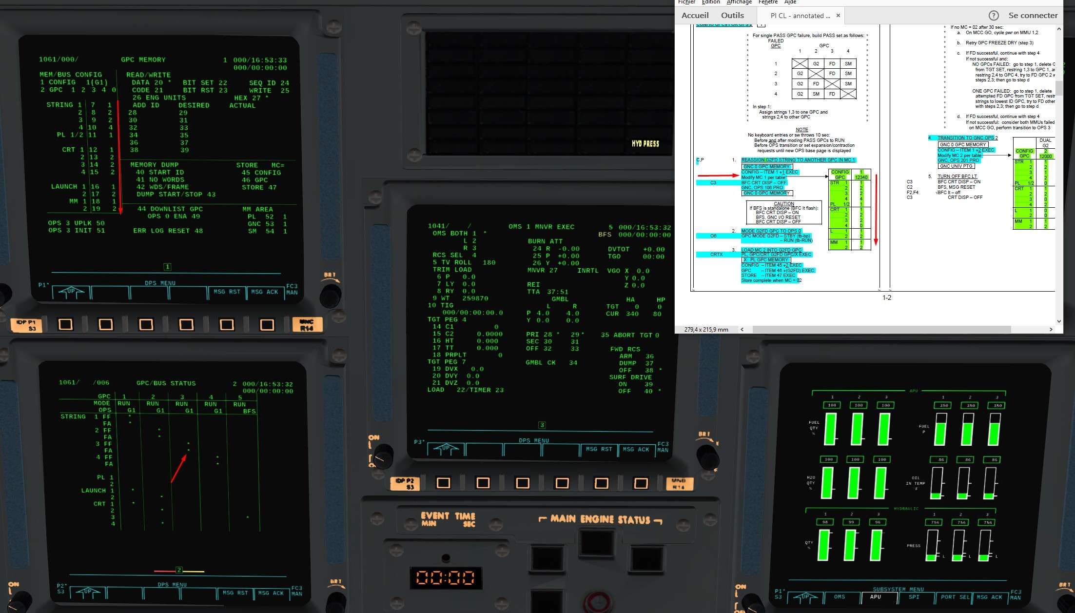
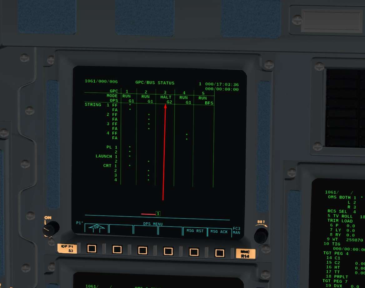
GPC3 is now freeze dried, let's put it in Halt for good

efXLRm.jpg


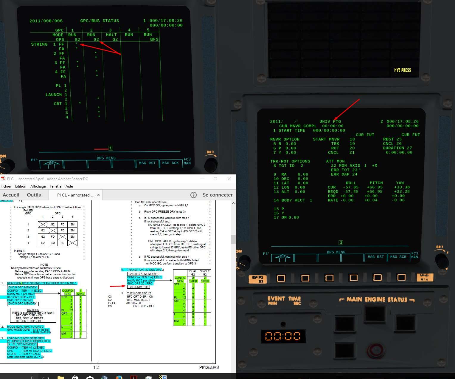
And the results of the Freeze Dried via Spec 6
GPC 3 is in Halt mode, with OPS 2 software loaded, and it is not emitting on nay buses. Job done.

y5VSqA.jpg


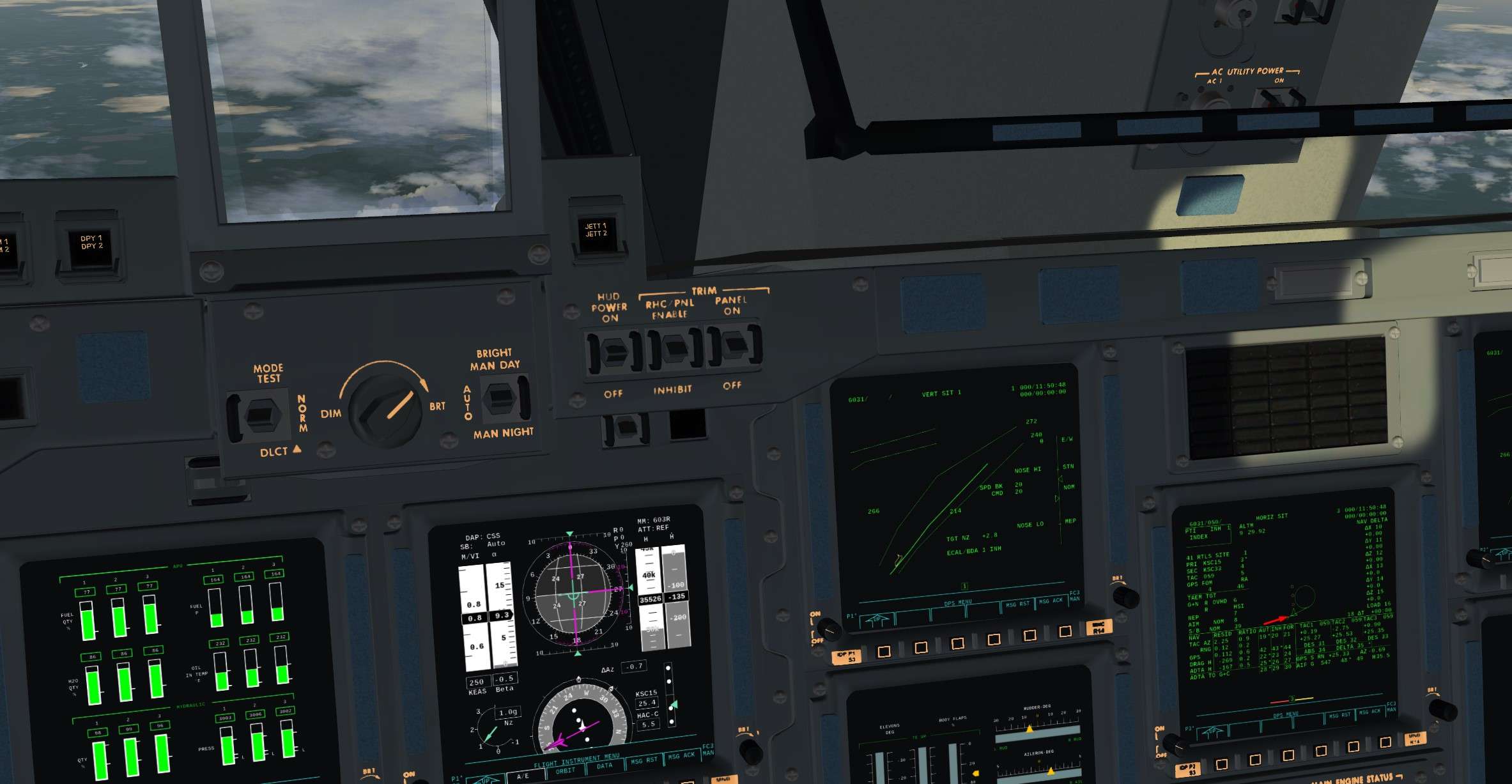
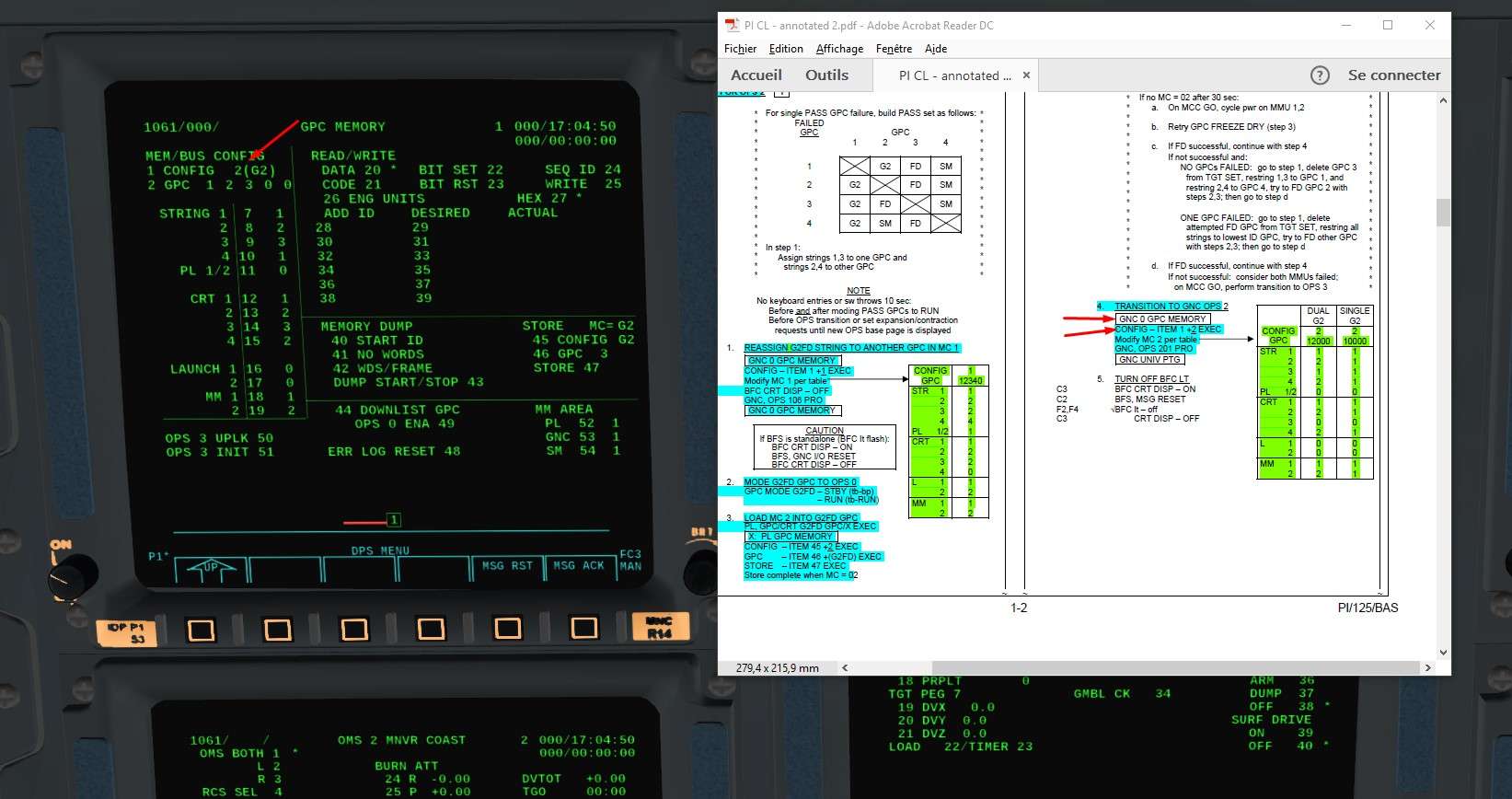
Now, we will transition GPC 1 and 2 towards the Guidance and Navigation (GNC) OPS 2 Software
Same as before, SPEC 0 EXEC on CRT 1 and we check that the NBAT is correct

dArXnT.jpg


w8vLss.jpg


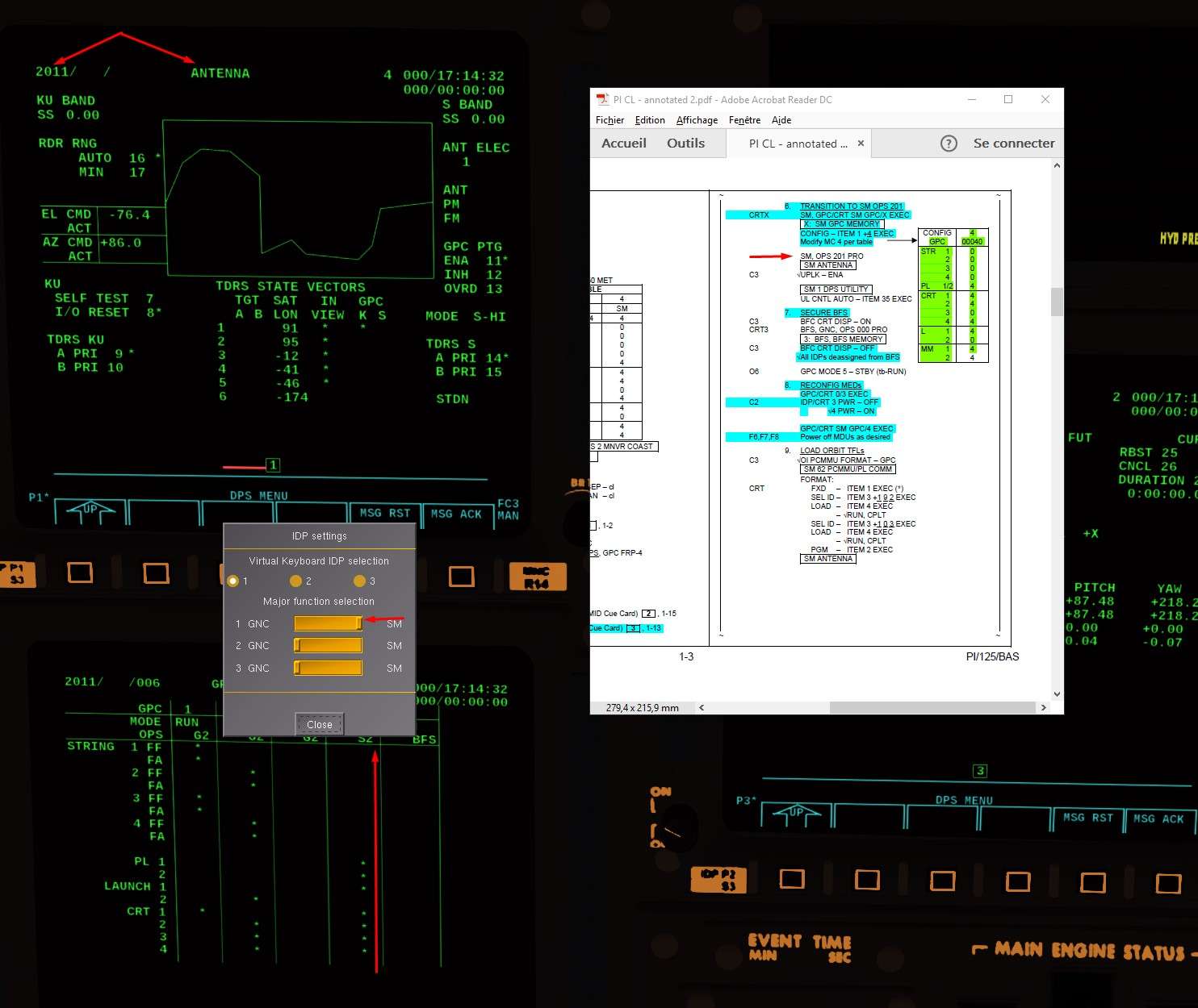
Then we can transition towards OPS 2 with OPS 201 PRO
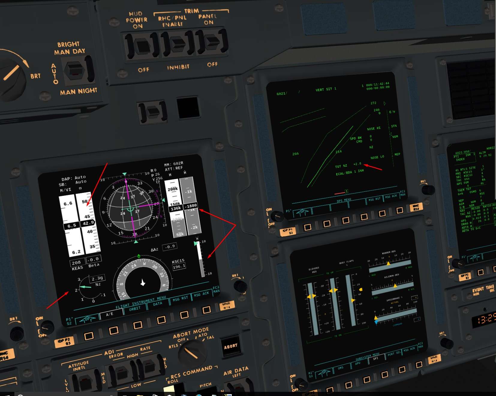
We can verify that we are well in OPS 2 and UNIV PTG soft.

97QXFf.jpg


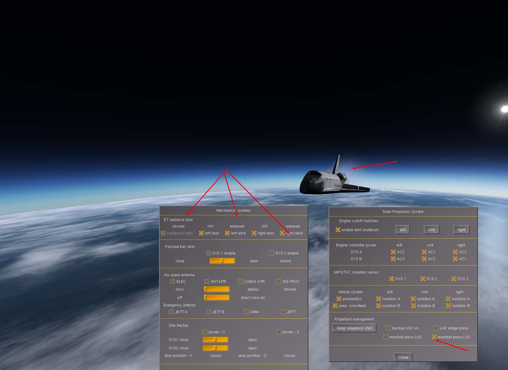
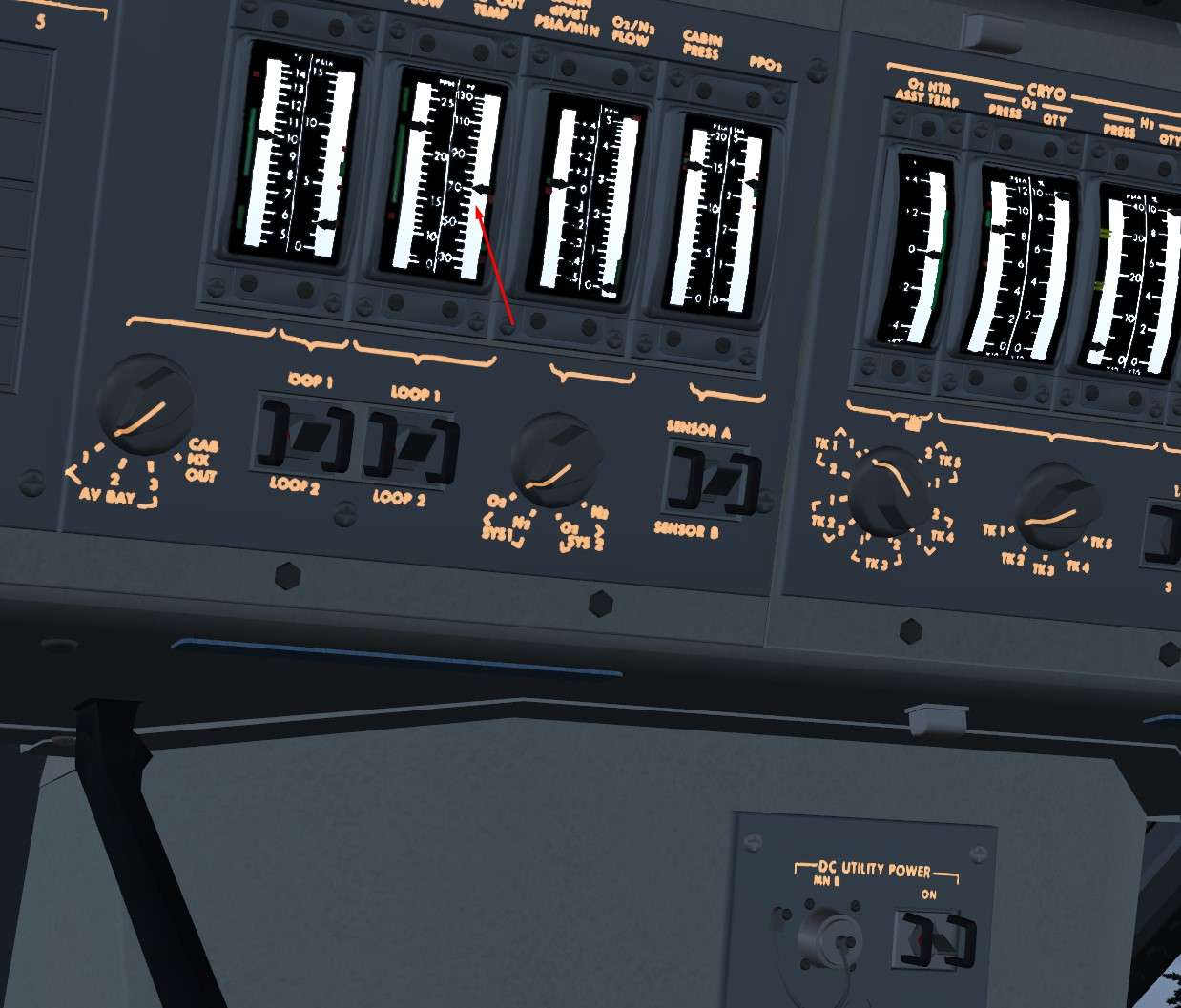
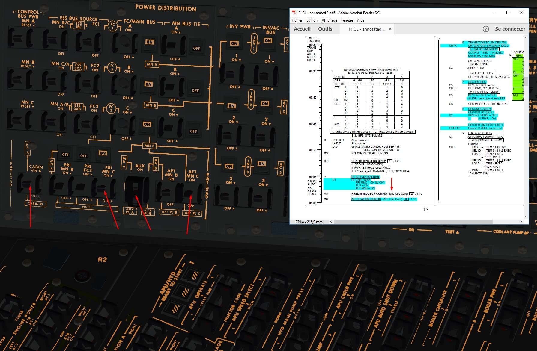
Next Step in the checks is to activate some Payload Bus on the electrical panel

93Y9Ve.jpg


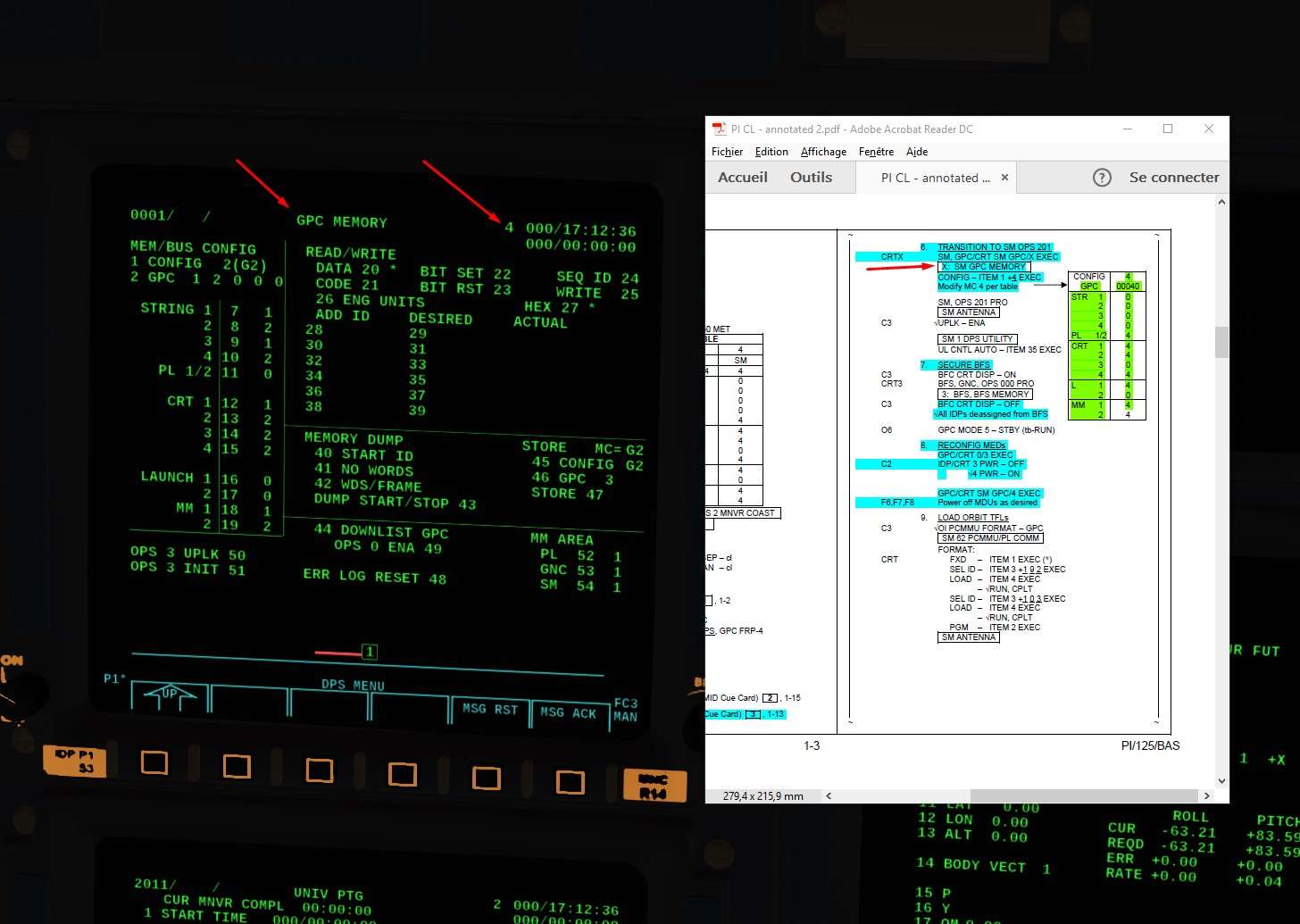
Almost there, we need now to configure the GPC 4 to run the System Management (SM) software in OPS 2
If not, we will not have access to various monitoring pages concerning all the Orbiter parameters

For that, choose a CRT where to display the GPC 4
I choosed the CRT1
Like before with the GPC 3, we do GPC/CRT 41 EXEC

HLYcSg.jpg


Then we reconfigure the NBAT
GPC 4 will not emit on Flight Criticals Buses ( FF), it will not have a role in Guidance and Navigation, not part of the Redundant set composed of GPC 1 and 2
It will emit only on Payload buses ( monitoring parameters like fuel cells, OMS, etc), CRT ( to display what it wants to show us), Launch Data buses ( to control the RMS) and Mass Memory ( to download the SM OPS 2 software)

h6U0ea.jpg


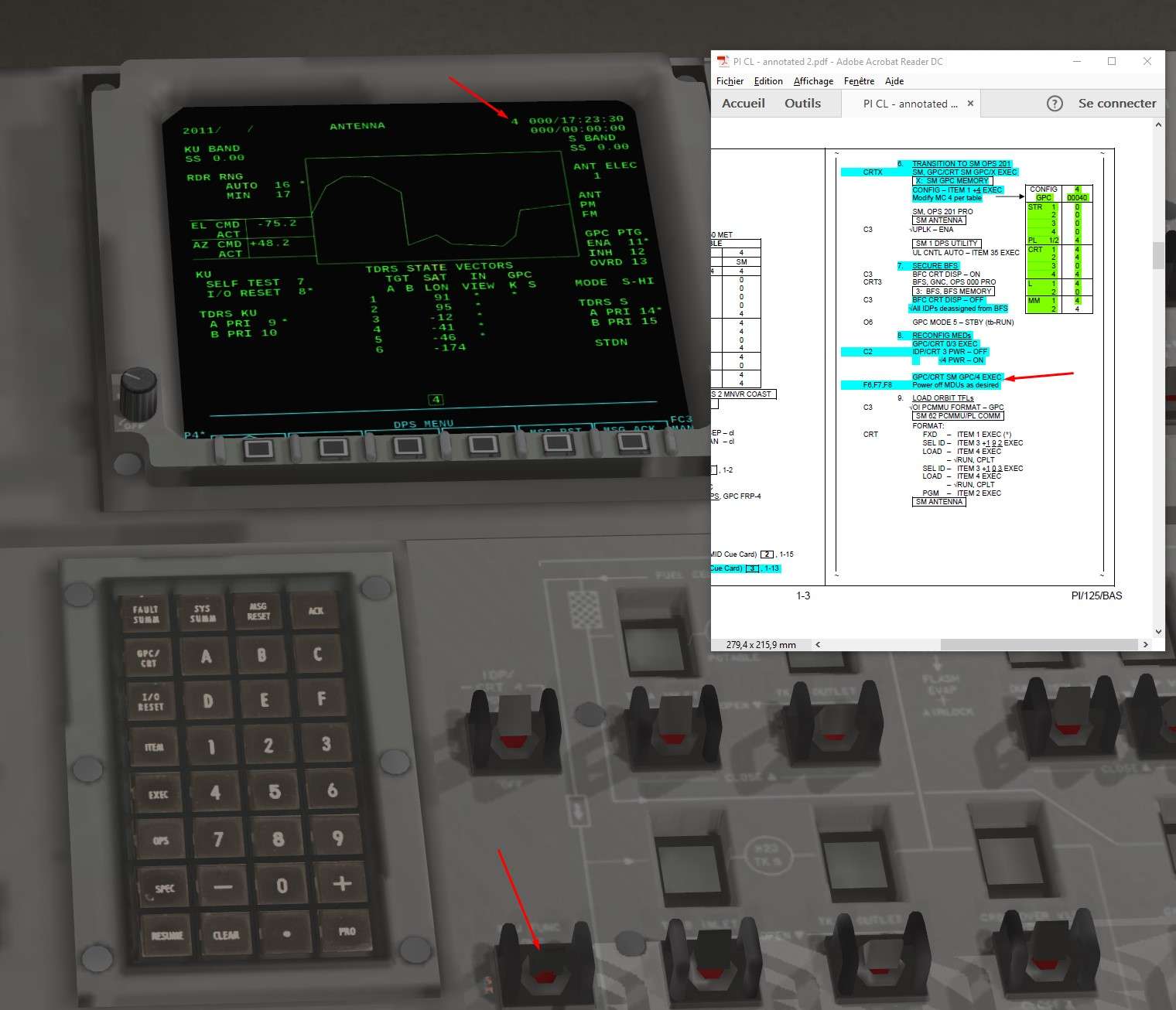
Finally, verify you are in SM major function on the CRT you are working on ( 1 here) and transition to SM OPS 2 via OPS 201 PRO
Verify Antenna program

02Dy3k.jpg


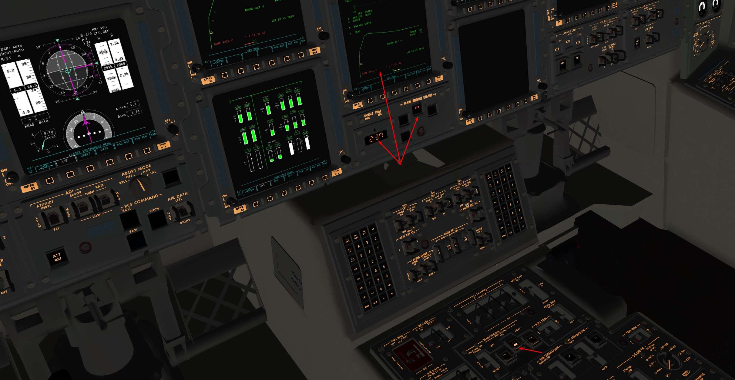
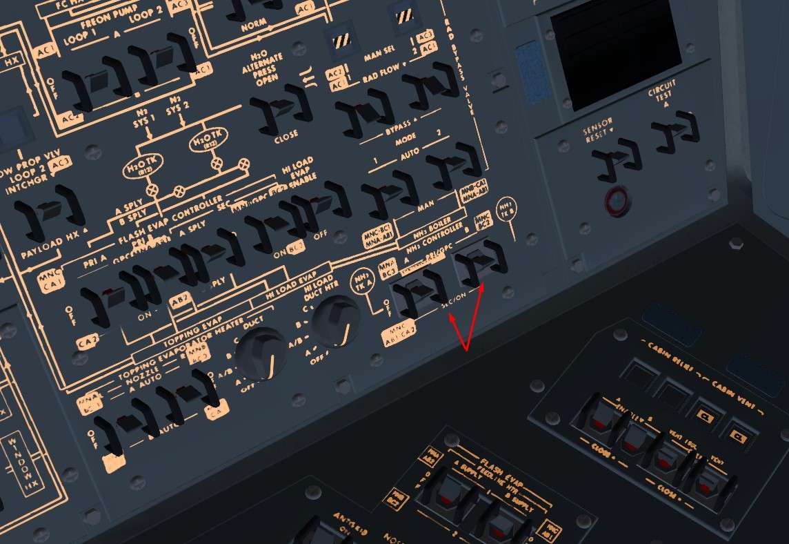
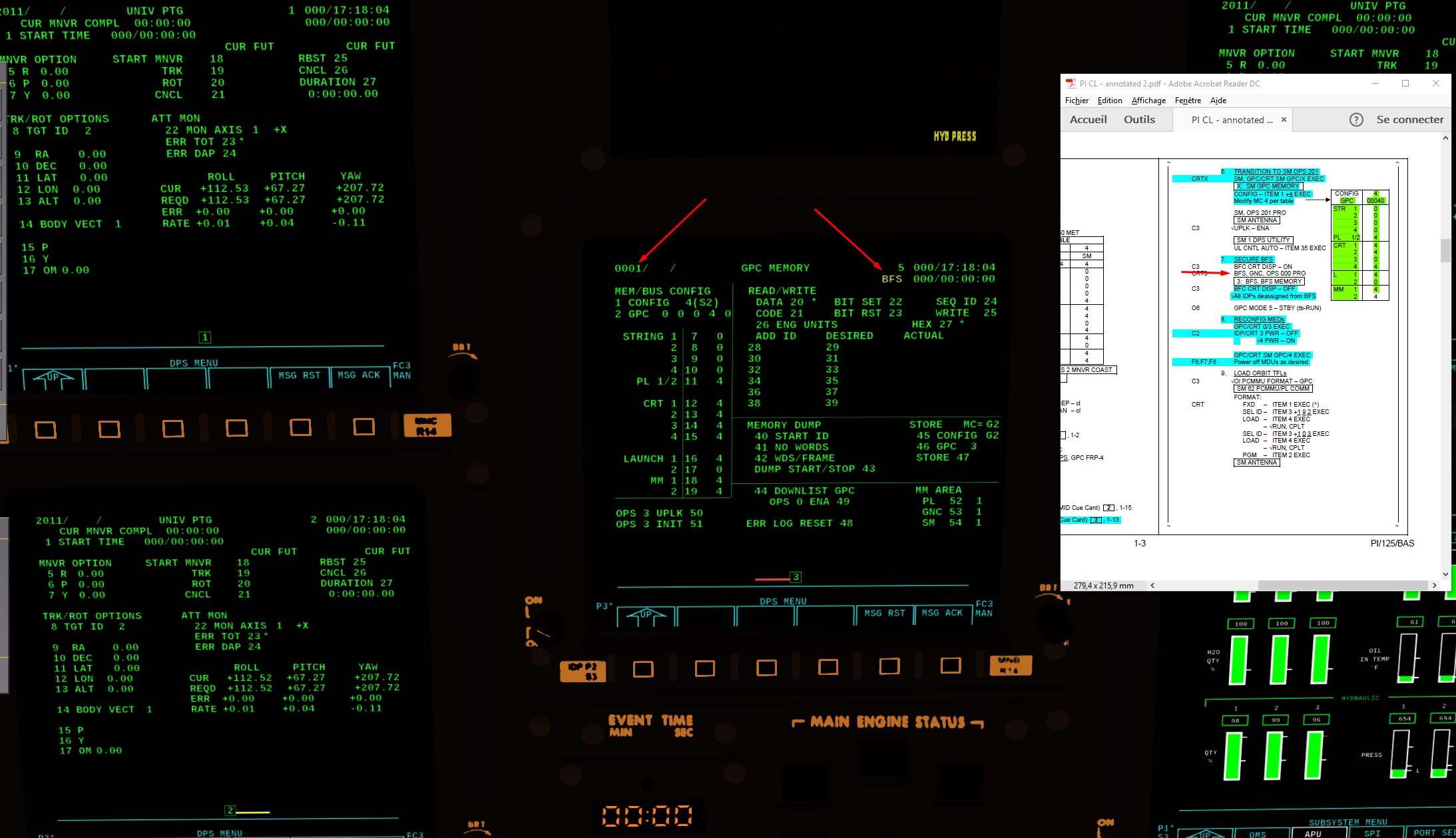
Almost there, BFS needs to be secure now
Display it via the switch we saw before on the pedestal (C3), you should see the BFS on CRT 3
Then load it with OPS 0 PRO
Unlike the GPC 3 , is not part of Redundant set and Common set, so no risk of switching the others GPC in OPS 0 also

lwDK4D.jpg


And switch off again the BFS CRT switch.

You might have a poll error when you switch it off
In that case, no worries, just do an OPS 2 recall on CRT 1 OPS 201 PRO to reload the correct NBAT, and GPC 2 should be polling again the CRT 3

WIlTgp.jpg


Now, we gonna secure and switch off the CRT 3 not used in Obit
GPC/CRT 03 EXEC to deasign any GPC of CRT 3 and turned it off

5RBx78.jpg


Let's check that the CRT 4 is turned on, with the Major Funtion in SM
By convention also, this CRT is the prefered one in Orbit to access to the SM

F62Ovw.jpg


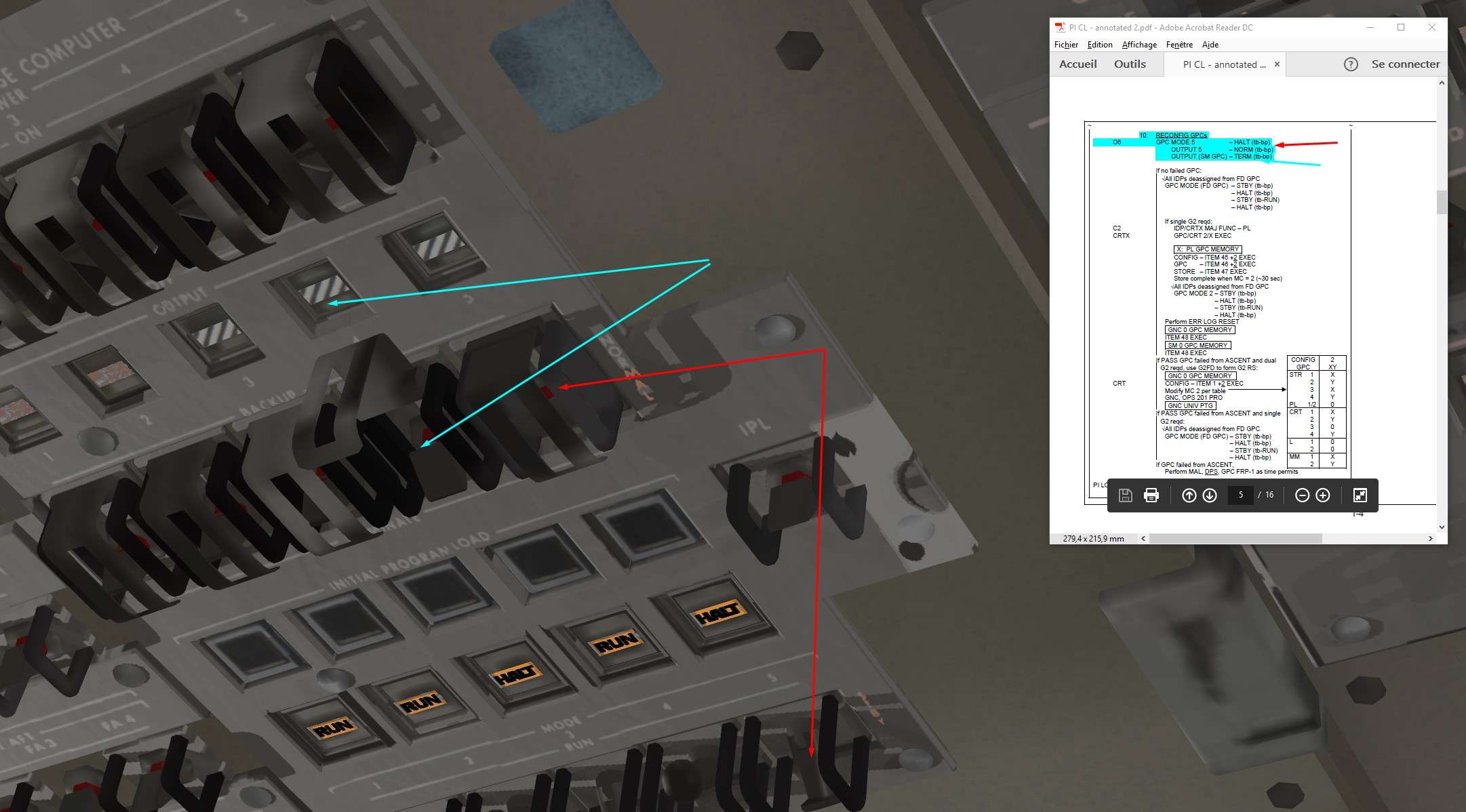
And final step now, GPC 5 ( BFS) will be put in Halt mode and GPC 4 ( SM) will be put in Terminate Output
Terminate means it can't emit on Flight Critical Buses ( just a precaution I guess because in the NBAT, it wasn't assign on any FF)

LSwi4J.jpg


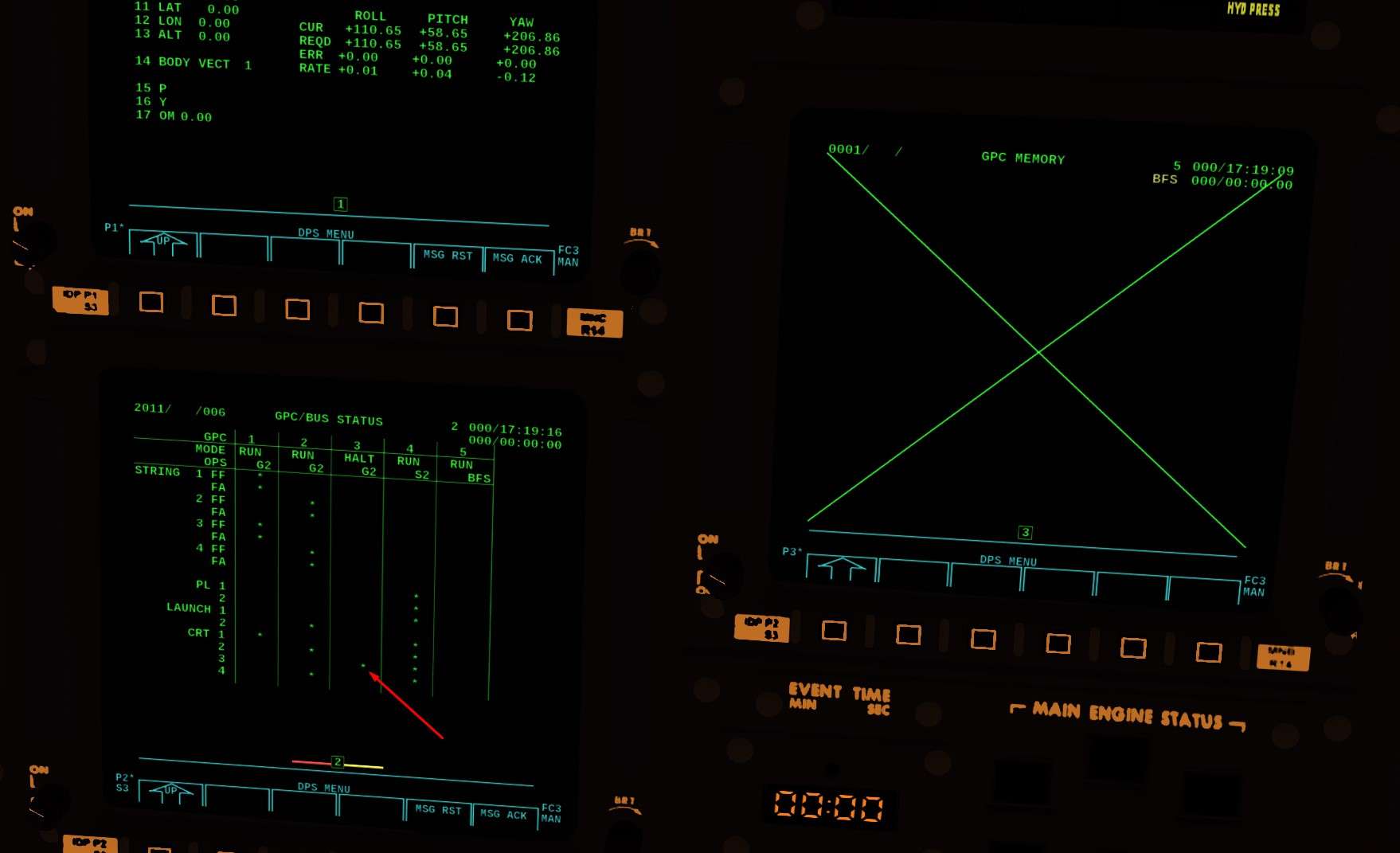
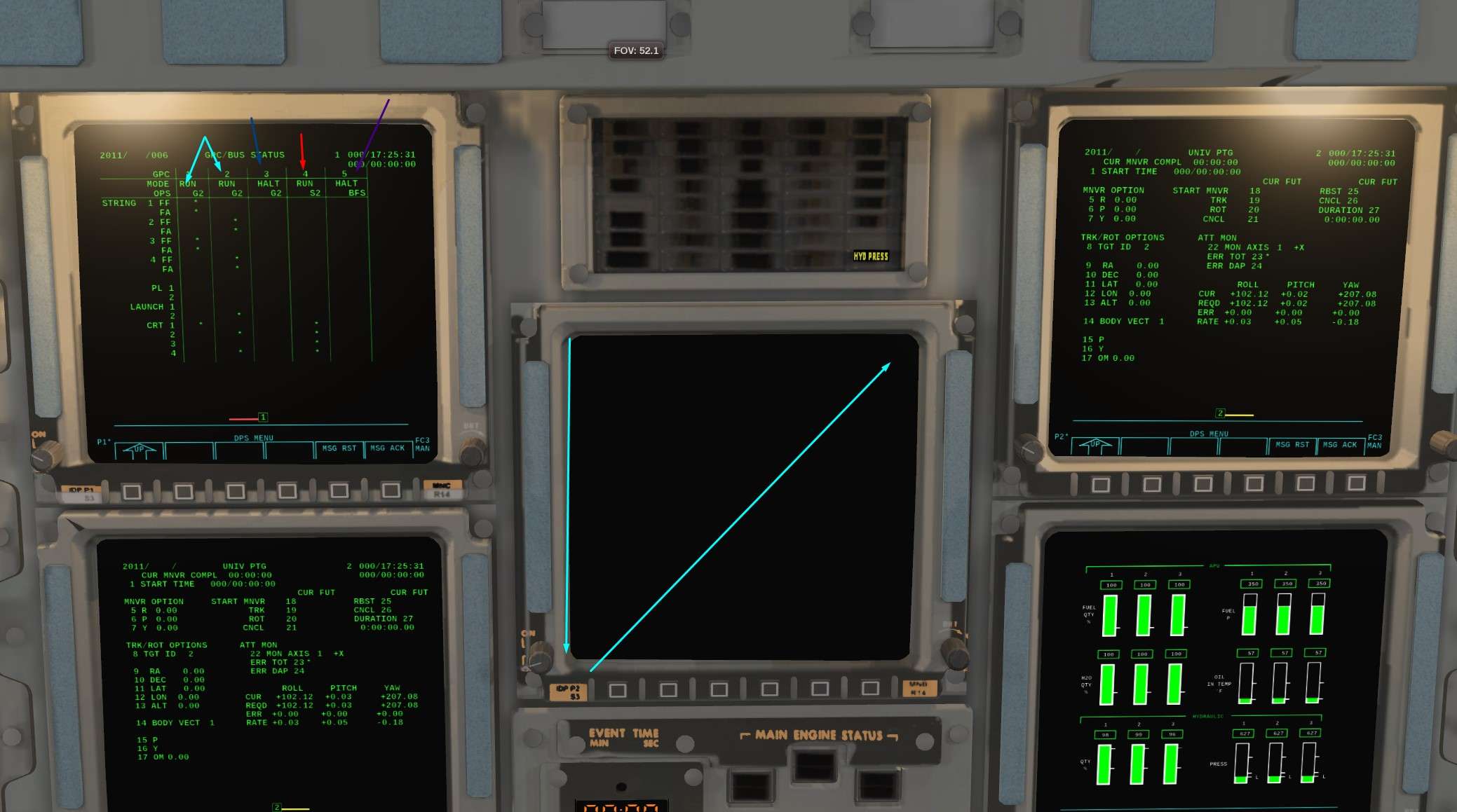
Here are, fully configured ( DPS wise) for Orbit OPS

GPC 1 and 2 for Guidance and Navigation
GPC 3 FD
GPC 4 for System Management
GPC 5 Halt

And CRT 3 turned Off

All of that is sum up on Spec 6 page ( PL 1/2 and L1 should have a Star in GPC 4 column, don't not why it isn't on the screen but in game it was correct)
Well done Thorsten, Fantastic Work

KtSl27.jpg
 

Thorsten

Active member
Joined
Dec 7, 2013
Messages
785
Reaction score
56
Points
43
Just returned from Lelystad (Netherlands) where we (among other things) presented a Shuttle RTLS live on the FSWeekend event - on an IMAX-sized screen and a movie theater surround sound system in front of a full auditorium (I am flying, Durk Talsma giving the Dutch voiceover).

23172725_1577706945623560_5513662500579876818_n.jpg


23130792_1577707028956885_1822853964449708365_n.jpg


23131869_1577707065623548_8643320297077871908_n.jpg


23167966_1577707045623550_1930347859980590490_n.jpg


Since that's probably the best equipment I'll ever have plugged into my laptop, I have to make the memory count :lol:

---------- Post added at 06:27 PM ---------- Previous post was at 08:04 AM ----------

Seems we even have a partial recording of the event (for the Shuttle experts - please keep in mind that there were kids in the audience as well, which is why many things are a bit simplified).


Thorsten

Active member
Joined
Dec 7, 2013
Messages
785
Reaction score
56
Points
43
Quick update:

I've started on an offline numerical tool for low orbit trajectory computations today - this will ultimately allow to simulate the capabilities of mission control for the Shuttle in terms of providing precise burn targets (both PEG-4 and PEG-7) for insertion, de-orbit and rendezvous.

I've ran a few quick checks, running with 0.01 second timestep is quite feasible, does a full orbit in an unmeasurable time and gives essentially unmeasurable errors when trying to close an ideal 2-body orbit, so this is a good base for fits.

The code is in C++ and I will eventually release it under GPL V2+ - being a Linux person I won't supply a windows binary, but I'm using only standard libs, so if anyone cares to do so for use with Orbiter, he's most welcome. I'll post status updates here.
 

Thorsten

Active member
Joined
Dec 7, 2013
Messages
785
Reaction score
56
Points
43
The tool is making reasonable progress, I've now benchmark-tested the core numerics and done some utility code.

The configuration is done via writing a config file with an ascii editor and invoking the program from the commandline. The output is either written to console or, if requested, dumped into a data file.

Here's an example of an insertion burn test

Code:
input

config

units imperial
gravity_model J3
earth_model IERS
burn_model impulse
plot2d_resolution 200

state_vector

x 21425960.92
y 62204.24
z 55720.39

vx 56.1346
vy 19227.92
vz 17665.56

burn_peg7

name OMS2
time 2550.0
dx 450.0
dz 0.0
dy 0.0

output

plot2d
file insertion_impulse.dat	
x time
y alt

end

and this is the resulting altitude vs. time for various cases. The first curves compare J3 gravity vs. spherical gravity (in both cases assuming an IERS 2003 reference ellipsoid for the shape of Earth).

The second set of curves compares finite-duraction burns with the impulse approximation of instantaneous burns - the first test case keeps the same TIG as the finite duration burn, the second shifts TIG to half the burn duration (and this gives almost the same result back).

insertion.jpg


Since you can plot any orbital element or other quantity against any other, this is also a fairly instructive way to study what J2 and J3 gravity terms do.

In terms of testing, I've done closure of an analytical orbit (spherical gravity and spherical earth shape) and over a single orbit I see apogee altitude differences of < 50 cm (they might be even smaller, but the test wasn't able to measure that).

I've also compared altitude vs. longitude against a JSBSim solution of a post-MECO solution (this is a fairly complex test, because it involved rotation of Earth as well as the ellipsoid shape) and I'm seeing differences on the permille level (which might actually be genuine simulated physics of JSBSim because drag isn't quite zero yet at 150 km altitude...).

I'll still need to add some fit routines, do some more testing, and then we can have a first release.
 

Thorsten

Active member
Joined
Dec 7, 2013
Messages
785
Reaction score
56
Points
43
... and now I can do optimized de-orbit PEG-4 fits.

The input for this is a trial PEG-4 target set (where TIG just marks the beginning of the search interval), a landing site (lat, lon) and the desired REI to the site, the fit then automatically adjusts TIG such that the REI target is met and at the same time optimizes the thetaT angle such that basically only a prograde burn is needed.

This gets me into an EI with the desired REI, altitude and flightpath angle as per c1/c2 at typically < 40 iterations even from a fairly eccentric orbit in J3 gravity (taking into account Earth rotation and shape of course).
 
Last edited:
Top