How do the Crawler braking systems work? The cab has both a foot pedal and a brake PBI. I think the foot pedal controls the normal brakes, and the PBI sets the parking brake; is this correct? Also, does the 'BRAKE ON' light correspond to the parking brake or the normal brakes?
You are using an out of date browser. It may not display this or other websites correctly.
You should upgrade or use an alternative browser.
You should upgrade or use an alternative browser.
SSU Crawler Transporter development
- Thread starter DaveS
- Start date
- Joined
- Feb 4, 2008
- Messages
- 9,762
- Reaction score
- 1,031
- Points
- 203
According to my research, the BRAKE PBI and light is for the parking brake which acts like the parking brake on a car. The service brake pedel works just like the brake pedal on a car.How do the Crawler braking systems work? The cab has both a foot pedal and a brake PBI. I think the foot pedal controls the normal brakes, and the PBI sets the parking brake; is this correct? Also, does the 'BRAKE ON' light correspond to the parking brake or the normal brakes?
The SPEED CONTROL knob works very much like cruise control on car, it maintains a specific speed. So getting the C/T to a complete stop is done by setting the SPEED CONTROL knob to zero and applying the service brakes, or you can just let the C/T coast to a full stop.
---------- Post added 07-18-10 at 06:51 PM ---------- Previous post was 07-17-10 at 07:21 PM ----------
Two bugs noticed:
- In the Cab 3 view, the the steering mode PBIs doesn't work. You can to go to Cab 1 view to switch modes.
- Can't attach the MLP to the pad mount mechanisms following rollout. Example scenario posed below.
Code:
BEGIN_DESC
Orbiter saved state at T = 28909
END_DESC

BEGIN_ENVIRONMENT
  System Sol
  Date MJD 44602.8751595956
  Context SSU
END_ENVIRONMENT

BEGIN_FOCUS
  Ship Crawler-Transporter
END_FOCUS

BEGIN_CAMERA
  TARGET Crawler-Transporter
  MODE Extern
  POS 4.41 -121.23 -8.79
  TRACKMODE TargetRelative
  FOV 20.00
END_CAMERA

BEGIN_VC
END_VC

BEGIN_SHIPS
Crawler-Transporter:SSU_CT
  STATUS Orbiting Earth
  RPOS 4974398.28 3820094.06 -1119031.12
  RVEL 185.673 -144.137 333.319
  AROT -127.55 -25.26 120.31
  AFCMODE 7
  NAVFREQ 0 0
  VELOCITY 0.00
  STEERING_ACTUAL 0.000000 0.000000
  STEERING_COMMANDED 0.000000 0.000000
  JACK_HEIGHT 1.80
  HEIGHT 15.400000 15.400000
  ANGLE 0.000000 0.000000
  VIEWPOS 1
  STANDALONE 0
  GROUND_POS 0.4993108337 -1.4068062766 3.1444066419
  REVERSE_ATTACH
@SUBSYSTEM Engine
  TGT_VELOCITY -0.00
  ENGINE_POWER -0.00
@ENDSUBSYSTEM        ;Engine
  @PANEL FWD_CAB_CTR
  @ENDPANEL
  @PANEL FWD_CAB_RIGHT
  "Crab" SET
  @ENDPANEL
  @PANEL REAR_CAB
  @ENDPANEL
  @PANEL REAR_CAB_RIGHT
  "Crab" SET
  @ENDPANEL
END
LC39A:SSU_Pad
  STATUS Landed Earth
  POS -80.6040720 28.6083850
  HEADING 270.00
  AFCMODE 7
  NAVFREQ 0 0
  ACCESS_ARM 1 1.0000
  GVA 1 1.0000
  VENTHOOD 0 0.0000
  FSS_OWP 0 0.0000
  RSS_OWP 0 0.0000
  RSS 1 1.0000
  FSS_GH2 0 0.0000
  FSS_IAA 0 0.0000
  GOX_SEQUENCE 0
END
VAB:Spacecraft\Spacecraft3
  STATUS Landed Earth
  POS -80.6509880 28.5860940
  HEADING 76.00
  AFCMODE 7
  NAVFREQ 0 0
  RCS 1
  CTRL_SURFACE 1
  CONFIGURATION 1
  CURRENT_PAYLOAD 0
  SEQ 0 -2 0.000000
  SEQ 1 -2 0.000000
  SEQ 2 2 0.958570
  SEQ 3 2 0.998053
END
MLP_stands:VAB_MLP_stands
  STATUS Landed Earth
  POS -80.6510180 28.5860840
  HEADING 76.00
  AFCMODE 7
  NAVFREQ 0 0
END
MLP-2:Atlantis_MLP
  STATUS Orbiting Earth
  RPOS 4974409.37 3820102.58 -1119033.62
  RVEL 185.673 -144.137 333.319
  AROT 52.45 25.26 59.69
  ATTACHED 0:0,Crawler-Transporter
  AFCMODE 7
  NAVFREQ 0 0
  T0_UMB 0 0.0000
END
Columbia:SpaceShuttleUltra
  STATUS Orbiting Earth
  RPOS 4974431.37 3820113.40 -1119041.21
  RVEL 185.673 -144.137 333.319
  AROT 106.33 -51.33 43.07
  ATTACHED 0:0,MLP-2
  AFCMODE 7
  PRPLEVEL 0:1.000000 1:1.000000 2:1.000000 3:0.982776 4:0.982638 5:0.982495 6:1.000000 7:1.000000 8:1.000000 11:0.020000
  NAVFREQ 0 0
  MISSION STS-1
  CONFIGURATION 0
  MET 0.000000
  WING_NAME Atlantis
  GEAR 0 0.0000
  OPS 101
  AUTOPILOT 28.650000 80.500000 103000.000000 7859.700000 0.730000
  ASSIST 0.000000 0.000000
  THROTTLE_BUCKET 834.000000 1174.000000
  HEADS_UP 328083.989501
  TGT_ID 2
  BODY_VECT 1
  ROLL 0.000000
  PITCH 0.000000
  YAW 0.000000
  P_ANGLE 0.000000
  Y_ANGLE 0.000000
  OM_ANGLE -1.000000
  DAP MODE 0 0
  ROT MODE 0 0 0
  TRANS MODE 0 0 0
  CONTROL MODE 1
   PAYLOAD CACTIVE1 8.000000 0.000000 0
   PAYLOAD CACTIVE2 0.000000 0.000000 0
   PAYLOAD CACTIVE3 -8.000000 0.000000 0
   PAYLOAD CPASSIVE1 4.000000 0.000000 0
   PAYLOAD CPASSIVE2 2.000000 0.000000 0
   PAYLOAD CPASSIVE3 -6.000000 0.000000 0
   PAYLOAD CPASSIVE4 7.000000 0.000000 0
   PAYLOAD PORT1 3.000000 0.000000 0
   PAYLOAD PORT2 -2.000000 0.000000 0
   PAYLOAD PORT3 -8.000000 0.000000 0
   PAYLOAD PORT4 7.000000 0.000000 0
   PAYLOAD STBD1 3.000000 0.000000 0
   PAYLOAD STBD2 -2.000000 0.000000 0
   PAYLOAD STBD3 -8.000000 0.000000 0
   PAYLOAD STBD4 0.000000 0.000000 0
  PLBD_CAM 0.0000 0.0000 0.0000 0.0000 0.0000 0.0000 0.0000 0.0000
@SUBSYSTEM MPS_C
@ENDSUBSYSTEM        ;MPS_C
@SUBSYSTEM MPS_L
@ENDSUBSYSTEM        ;MPS_L
@SUBSYSTEM MPS_R
@ENDSUBSYSTEM        ;MPS_R
@SUBSYSTEM FMC1
@ENDSUBSYSTEM        ;FMC1
@SUBSYSTEM FMC2
@ENDSUBSYSTEM        ;FMC2
@SUBSYSTEM FMC3
@ENDSUBSYSTEM        ;FMC3
@SUBSYSTEM MMC1
@ENDSUBSYSTEM        ;MMC1
@SUBSYSTEM MMC2
@ENDSUBSYSTEM        ;MMC2
@SUBSYSTEM MMC3
@ENDSUBSYSTEM        ;MMC3
@SUBSYSTEM MMC4
@ENDSUBSYSTEM        ;MMC4
@SUBSYSTEM AMC1
@ENDSUBSYSTEM        ;AMC1
@SUBSYSTEM AMC2
@ENDSUBSYSTEM        ;AMC2
@SUBSYSTEM AMC3
@ENDSUBSYSTEM        ;AMC3
@SUBSYSTEM FF1
@ENDSUBSYSTEM        ;FF1
@SUBSYSTEM FF2
@ENDSUBSYSTEM        ;FF2
@SUBSYSTEM FF3
@ENDSUBSYSTEM        ;FF3
@SUBSYSTEM FF4
@ENDSUBSYSTEM        ;FF4
@SUBSYSTEM FA1
@ENDSUBSYSTEM        ;FA1
@SUBSYSTEM FA2
@ENDSUBSYSTEM        ;FA2
@SUBSYSTEM FA3
@ENDSUBSYSTEM        ;FA3
@SUBSYSTEM FA4
@ENDSUBSYSTEM        ;FA4
@SUBSYSTEM PL1
@ENDSUBSYSTEM        ;PL1
@SUBSYSTEM PL2
@ENDSUBSYSTEM        ;PL2
@SUBSYSTEM LF1
@ENDSUBSYSTEM        ;LF1
@SUBSYSTEM LM1
@ENDSUBSYSTEM        ;LM1
@SUBSYSTEM LA1
@ENDSUBSYSTEM        ;LA1
@SUBSYSTEM OF1
@ENDSUBSYSTEM        ;OF1
@SUBSYSTEM OF2
@ENDSUBSYSTEM        ;OF2
@SUBSYSTEM OF3
@ENDSUBSYSTEM        ;OF3
@SUBSYSTEM OF4
@ENDSUBSYSTEM        ;OF4
@SUBSYSTEM OA1
@ENDSUBSYSTEM        ;OA1
@SUBSYSTEM OA2
@ENDSUBSYSTEM        ;OA2
@SUBSYSTEM OA3
@ENDSUBSYSTEM        ;OA3
@SUBSYSTEM LL1
@ENDSUBSYSTEM        ;LL1
@SUBSYSTEM LL2
@ENDSUBSYSTEM        ;LL2
@SUBSYSTEM LR1
@ENDSUBSYSTEM        ;LR1
@SUBSYSTEM LR2
@ENDSUBSYSTEM        ;LR2
@SUBSYSTEM EIU1
@ENDSUBSYSTEM        ;EIU1
@SUBSYSTEM EIU2
@ENDSUBSYSTEM        ;EIU2
@SUBSYSTEM EIU3
@ENDSUBSYSTEM        ;EIU3
@SUBSYSTEM MTU
  MET_RUNNING 0
  MET0 0.000000
  MET1 0.000000
  MET2 0.000000
EVENT_TIMER0 0.000000 DOWN STOPPED
EVENT_TIMER1 0.000000 DOWN STOPPED
@ENDSUBSYSTEM        ;MTU
@SUBSYSTEM IDP1
  IDP1 SPEC 65535
  IDP1 DISP 65535
@ENDSUBSYSTEM        ;IDP1
@SUBSYSTEM IDP2
  IDP2 SPEC 65535
  IDP2 DISP 65535
@ENDSUBSYSTEM        ;IDP2
@SUBSYSTEM IDP3
  IDP3 SPEC 65535
  IDP3 DISP 65535
@ENDSUBSYSTEM        ;IDP3
@SUBSYSTEM IDP4
  IDP4 SPEC 65535
  IDP4 DISP 65535
@ENDSUBSYSTEM        ;IDP4
@SUBSYSTEM IMU1
@ENDSUBSYSTEM        ;IMU1
@SUBSYSTEM IMU2
@ENDSUBSYSTEM        ;IMU2
@SUBSYSTEM IMU3
@ENDSUBSYSTEM        ;IMU3
@SUBSYSTEM GPC1
@ENDSUBSYSTEM        ;GPC1
@SUBSYSTEM GPC2
@ENDSUBSYSTEM        ;GPC2
@SUBSYSTEM GPC3
@ENDSUBSYSTEM        ;GPC3
@SUBSYSTEM GPC4
@ENDSUBSYSTEM        ;GPC4
@SUBSYSTEM GPC5
@ENDSUBSYSTEM        ;GPC5
@SUBSYSTEM ODS
  RING_STATE -1 0.0000
@ENDSUBSYSTEM        ;ODS
@SUBSYSTEM ADPS
  LEFT_AIRDATAPROBE 1 3 0.000000
  RIGHT_AIRDATAPROBE 1 3 0.000000
@ENDSUBSYSTEM        ;ADPS
@SUBSYSTEM ETUmbDoors
  ET_DOORS 1.000000 1.000000
  ET_DOOR_LATCHES 1.000000 1.000000 1.000000
@ENDSUBSYSTEM        ;ETUmbDoors
@SUBSYSTEM -YStarTrackerDoorMotor
@ENDSUBSYSTEM        ;-YStarTrackerDoorMotor
@SUBSYSTEM -ZStarTrackerDoorMotor
@ENDSUBSYSTEM        ;-ZStarTrackerDoorMotor
@SUBSYSTEM ACBusSystem
@ENDSUBSYSTEM        ;ACBusSystem
@SUBSYSTEM INVERTER1
@ENDSUBSYSTEM        ;INVERTER1
@SUBSYSTEM INVERTER2
@ENDSUBSYSTEM        ;INVERTER2
@SUBSYSTEM INVERTER3
@ENDSUBSYSTEM        ;INVERTER3
@SUBSYSTEM APU1
  APU1_State 0
  APU1_FuelPress 0.000000
  APU1_HydPress 0.000000
  APU1_Speed 0.000000
@ENDSUBSYSTEM        ;APU1
@SUBSYSTEM APU2
  APU2_State 0
  APU2_FuelPress 0.000000
  APU2_HydPress 0.000000
  APU2_Speed 0.000000
@ENDSUBSYSTEM        ;APU2
@SUBSYSTEM APU3
  APU3_State 0
  APU3_FuelPress 0.000000
  APU3_HydPress 0.000000
  APU3_Speed 0.000000
@ENDSUBSYSTEM        ;APU3
@SUBSYSTEM WSB1
@ENDSUBSYSTEM        ;WSB1
@SUBSYSTEM WSB2
@ENDSUBSYSTEM        ;WSB2
@SUBSYSTEM WSB3
@ENDSUBSYSTEM        ;WSB3
@SUBSYSTEM LATCH0
  LATCH_STATE1 1 1.0000
  LATCH_STATE2 1 1.0000
  LATCH_STATE3 1 1.0000
  LATCH_STATE4 1 1.0000
  LATCH_STATE5 1 1.0000
@ENDSUBSYSTEM        ;LATCH0
@SUBSYSTEM LATCH1
  LATCH_STATE1 1 1.0000
  LATCH_STATE2 1 1.0000
  LATCH_STATE3 1 1.0000
  LATCH_STATE4 1 1.0000
  LATCH_STATE5 1 1.0000
@ENDSUBSYSTEM        ;LATCH1
@SUBSYSTEM LATCH2
  LATCH_STATE1 1 1.0000
  LATCH_STATE2 1 1.0000
  LATCH_STATE3 1 1.0000
  LATCH_STATE4 1 1.0000
  LATCH_STATE5 1 1.0000
@ENDSUBSYSTEM        ;LATCH2
  CRT_SEL 1 1
  @PANEL F2
  @ENDPANEL
  @PANEL F4
  @ENDPANEL
  @PANEL F6
  "Cdr Flt Cntlr Pwr" OFF
  @ENDPANEL
  @PANEL F7
  @ENDPANEL
  @PANEL F8
  "Plt Flt Cntlr Pwr" OFF
  @ENDPANEL
  @PANEL R2
  "Boiler1 N2 Supply" OFF
  "Boiler2 N2 Supply" OFF
  "Boiler3 N2 Supply" OFF
  "Boiler1 Cntlr" OFF
  "Boiler2 Cntlr" OFF
  "Boiler3 Cntlr" OFF
  "Boiler1 Cntlr Pwr/Htr" OFF
  "Boiler2 Cntlr Pwr/Htr" OFF
  "Boiler3 Cntlr Pwr/Htr" OFF
  "APU1 Run" OFF
  "APU2 Run" OFF
  "APU3 Run" OFF
  "Hyd Main Pump Press 1" NORM
  "Hyd Main Pump Press 2" NORM
  "Hyd Main Pump Press 3" NORM
  "APU1 Cntlr Pwr " OFF
  "APU2 Cntlr Pwr " OFF
  "APU3 Cntlr Pwr " OFF
  "APU1 Fuel Tank Valve" CLOSE
  "APU2 Fuel Tank Valve" CLOSE
  "APU3 Fuel Tank Valve" CLOSE
  "ET Umb Centerline Latch" GND
  "ET Umb Left Door" OFF
  "ET Umb Left Door Latch" OFF
  "ET Umb Right Door" OFF
  "ET Umb Right Door Latch" OFF
  "MPS Pwr Left AC2" [0]
  "MPS Pwr Ctr AC1" [0]
  "MPS Pwr Right AC3" [0]
  "MPS Pwr Left AC3" [0]
  "MPS Pwr Ctr AC2" [0]
  "MPS Pwr Right AC1" [0]
  "MPS He Isol A Left" GPC
  "MPS He Isol A Ctr" GPC
  "MPS He Isol A Right" GPC
  "MPS He Isol B Left" GPC
  "MPS He Isol B Ctr" GPC
  "MPS He Isol B Right" GPC
  @ENDPANEL
  @PANEL C3
  "LOMS Arm" ARM/PRESS
  "ROMS Arm" ARM/PRESS
  "LADP Stow Enable" INHIBIT
  "RADP Stow Enable" INHIBIT
  "LADP Deploy" STOW
  "RADP Deploy" STOW
  @ENDPANEL
  @PANEL O6
  "L GLRSHLD FLOOD" OFF
  "S TRK DR CNTL SYS1" CLOSE
  "S TRK DR CNTL SYS2" CLOSE
  "GPC_POWER_1_COVER" [0]
  "GPC_POWER_2_COVER" [0]
  "GPC_POWER_3_COVER" [0]
  "GPC_POWER_4_COVER" [0]
  "GPC_POWER_5_COVER" [0]
  "GPC POWER 1" ON
  "GPC POWER 2" ON
  "GPC POWER 3" ON
  "GPC POWER 4" ON
  "GPC POWER 5" ON
  "GPC_OUTPUT_1_COVER" [0]
  "GPC_OUTPUT_2_COVER" [0]
  "GPC_OUTPUT_3_COVER" [0]
  "GPC_OUTPUT_4_COVER" [0]
  "GPC_OUTPUT_5_COVER" [0]
  "GPC OUTPUT 1" NORMAL
  "GPC OUTPUT 2" NORMAL
  "GPC OUTPUT 3" NORMAL
  "GPC OUTPUT 4" NORMAL
  "GPC OUTPUT 5" NORMAL
  "IPL SOURCE" OFF
  "GPC MODE 1" STBY
  "GPC MODE 2" STBY
  "GPC MODE 3" STBY
  "GPC MODE 4" STBY
  "GPC MODE 5" STBY
  @ENDPANEL
  @PANEL R11
  @ENDPANEL
  @PANEL A6
  "SENSE" -X
  "Aft Flt Cntlr Pwr" OFF
  "Payload Ret Latch 1" OFF
  "Payload Ret Latch 2" OFF
  "Payload Ret Latch 3" OFF
  "Payload Ret Latch 4" OFF
  "Payload Ret Latch 5" OFF
  "Payload Select" 1
  @ENDPANEL
  @PANEL AftMDU
  @ENDPANEL
  @PANEL A7U
  @ENDPANEL
  @PANEL A7A3/A8A3
  "SYSTEM POWER MNA" [0]
  "SYSTEM POWER MNB" [0]
  "PYRO POWER MNA" [0]
  "PYRO POWER MNC" [0]
  "SYS1 VENT ISOL" [0]
  "SYS1 VENT" [0]
  "SYS2 VENT ISOL" [0]
  "SYS2 VENT" [0]
  "PSU POWER MNA" [0]
  "PSU POWER MNB" [0]
  "LIGHTS AIRLOCK 1-4" [0]
  "LIGHTS AIRLOCK 2-3" [0]
  "LIGHTS DOCKING TRUSS FWD" [0]
  "LIGHTS DOCKING TRUSS AFT" [0]
  "ARLK/TNL FAN A" [0]
  "ARLK/TNL FAN B" [0]
  "LIGHTS C/L VESTIBULE PORT" [0]
  "LIGHTS C/L VESTIBULE STBD" [0]
  "CNTL PNL PWR A" OFF
  "CNTL PNL PWR B" OFF
  "CNTL PNL PWR C" OFF
  "HTRS/DCU PWR H1" OFF
  "HTRS/DCU PWR H2/DCU" OFF
  "HTRS/DCU PWR H3/DCU" OFF
  "APDS PWR A" OFF
  "APDS PWR B" OFF
  "APDS PWR C" OFF
  "PYROS Ap" [0]
  "PYROS Bp" [0]
  "PYROS Cp" [0]
  @ENDPANEL
END
ET:Atlantis_Tank
  STATUS Orbiting Earth
  RPOS 4974435.02 3820118.20 -1119041.16
  RVEL 185.673 -144.137 333.319
  AROT 106.33 -51.33 43.07
  ATTACHED 0:20,Columbia
  AFCMODE 7
END
LSRB:Atlantis_LSRB
  STATUS Orbiting Earth
  RPOS 4974422.98 3820113.81 -1119044.77
  RVEL 185.673 -144.137 333.319
  AROT 106.33 -51.33 43.07
  ATTACHED 0:21,Columbia
  AFCMODE 7
  PRPLEVEL 1:1.000000
END
RSRB:Atlantis_RSRB
  STATUS Orbiting Earth
  RPOS 4974429.26 3820108.92 -1119033.55
  RVEL 185.673 -144.137 333.319
  AROT 106.33 -51.33 43.07
  ATTACHED 0:22,Columbia
  AFCMODE 7
  PRPLEVEL 1:1.000000
END
END_SHIPSBoth the cab views work for me. The MLP problem is because you're not close enough to the attach point; I'll change the distance limit so it's possible to attach the MLP without wasting a lot of time playing with the position.
- Joined
- Feb 4, 2008
- Messages
- 9,762
- Reaction score
- 1,031
- Points
- 203
Just how close do you need to be? The message on the screen indicates it's off by 2 m in the Z axis, when it is clearly parked dead-center on the pad mount mechanism and the MLP flange pins is just 5 cm off from the mount mechanisms.Both the cab views work for me. The MLP problem is because you're not close enough to the attach point; I'll change the distance limit so it's possible to attach the MLP without wasting a lot of time playing with the position.
And for me only the Cab 1 PBIs work. No matter where I click, the Cab 3 PBIs won't work.
Last edited:
were can i download the crawler
Logifech
Member
- Joined
- Nov 15, 2009
- Messages
- 161
- Reaction score
- 0
- Points
- 16
- Location
- Germany, NRW, Kempen
- Website
- patrick-omland.de
You can't download the crawler it's a part of SSU the crawler is still in work.
- Joined
- Feb 4, 2008
- Messages
- 9,762
- Reaction score
- 1,031
- Points
- 203
From the SSU SVN repository. But you'll have to compile the code yourself. And it requires that you have previous knowledge of how the C/T works as there's no manual(yet).were can i download the crawler
---------- Post added at 11:33 PM ---------- Previous post was at 10:44 PM ----------
Checked in a fix for the incorrect MLP attachment point on the C/T. Now the various sides on the MLP lines up with the correct sides on the C/T.
---------- Post added at 11:58 PM ---------- Previous post was at 11:33 PM ----------
After quite alot of moving the C/T with the MLP at the pad, I have concluded that the mount mechanisms are too far apart in the X-axis, making it impossible to line up the C/T correctly just by eyeballing the C/T's position relative to the mounts.
It would be great if you could implement a rudimentary version of the LDS display so this positioning error could be confirmed conclusively.
I think part of the problem is that the distance between the attachment points is not being computed correctly, although I haven't confirmed this yet.
---------- Post added at 06:35 PM ---------- Previous post was at 06:12 PM ----------
I think the main problem here is that the distance between the Crawler and MLP attach points is calculated incorrectly; it should be about 0.7m in the scenario posted, whereas it's calculated as about 4m in the z-axis and 2m in the y-axis. The corrected code should be checked in today.
---------- Post added at 08:13 PM ---------- Previous post was at 06:35 PM ----------
Checked in corrected version. The brakes are also implemented now, they can be activated by holding down 'B'.
- Joined
- Feb 4, 2008
- Messages
- 9,762
- Reaction score
- 1,031
- Points
- 203
Corrected version works fine, although we got another case of flipped attachment point on the pad. Brakes work fine.
Another bug noticed though: In Cab 3 in the desired steering angle display doesn't work, at least not in the INDEP. Still can't change steering modes in the Cab 3.
Just so there's no confusion: Cab 3 is the one that does not look towards OPF-3 in the CT-1 roadtest scenario. It is accessed by pressing the "2" key.
---------- Post added at 01:10 PM ---------- Previous post was at 12:50 PM ----------
Seems like I spoke too soon on the attachment point problem. It is not fixed. Now it flips the MLP around 180°s when you try to attach it to the pad mounts.
The Cab 3 problem is because pressing '2' changes the camera position, but the VC still thinks you're in Cab 1. Using CRTL+Arrow keys to move works. I'll change the code to handle this.Corrected version works fine, although we got another case of flipped attachment point on the pad. Brakes work fine.
Another bug noticed though: In Cab 3 in the desired steering angle display doesn't work, at least not in the INDEP. Still can't change steering modes in the Cab 3.
Just so there's no confusion: Cab 3 is the one that does not look towards OPF-3 in the CT-1 roadtest scenario. It is accessed by pressing the "2" key.
---------- Post added at 01:10 PM ---------- Previous post was at 12:50 PM ----------
Seems like I spoke too soon on the attachment point problem. It is not fixed. Now it flips the MLP around 180°s when you try to attach it to the pad mounts.
I think the attachment point flipping comes from the change you made yesterday. At the moment, when attaching the MLP, the Crawler checks the attachment point rotation and changes the rotation of the Crawler attach point so the MLP doesn't turn around. This is because the Crawler could theoretically be oriented in one of two directions when picking up the MLP. I can change the code so this doesn't occur, but then orienting the Crawler the wrong way could cause the MLP to flip when it's detached from the the VAB mounts.
- Joined
- Feb 4, 2008
- Messages
- 9,762
- Reaction score
- 1,031
- Points
- 203
Well, this won't happen as Side 3 of the C/T and MLP always faces out of the High Bay as that's how the mounts are set-up in the VAB bays, the refurb sites and the pads.This is because the Crawler could theoretically be oriented in one of two directions when picking up the MLP. I can change the code so this doesn't occur, but then orienting the Crawler the wrong way could cause the MLP to flip when it's detached from the the VAB mounts.
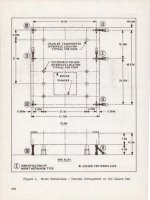
Length-wise, the mounts do not have equal distance between them. The center mounts are closer to the Side 3 mounts than the Side 1 mounts rather than being an equal distance from each other.
So the mount flanges on the platform would never line up with the mounts if you came in the wrong way. So the C/T is never turned around but always maintains a specific orientation WRT to the platform.
As you probably have noticed on the new meshes, they have the MLP stairs added on Sides 1 and 3. For the Apollo program, the C/T was located closer to Side 3 of the MLP so that the stairs on Side 3 could be lined up properly with a set of stairs on Side 3 of the MLP.
Today it's the other way around, C/T is closer to Side 1 and there's a new set of stairs located there to access the cryo pipes on Side 1 of the MLP.
Starting to make sense doesn't it? So the C/T has never been completely identical on both sides.
Attachments
OK, thanks. I was thinking the MLP could be attached regardless of the Crawler orientation; I'll fix this.
- Joined
- Feb 4, 2008
- Messages
- 9,762
- Reaction score
- 1,031
- Points
- 203
Checked in a corrected version of the attachment code; can you make sure the direction is correct? I haven't changed the VC code yet.
- Joined
- Feb 4, 2008
- Messages
- 9,762
- Reaction score
- 1,031
- Points
- 203
Works perfectly now, thanks!Checked in a corrected version of the attachment code; can you make sure the direction is correct? I haven't changed the VC code yet.
You can't, at the moment. I'll add this capability.
How do you think the mesh should be specified? The scenario file is the most obvious option, but we can also use the mission file. I'm thinking it might be better to reserve the mission file for shuttle parameters, though.
How do you think the mesh should be specified? The scenario file is the most obvious option, but we can also use the mission file. I'm thinking it might be better to reserve the mission file for shuttle parameters, though.
Last edited:
- Joined
- Feb 4, 2008
- Messages
- 9,762
- Reaction score
- 1,031
- Points
- 203
Scenario file will be fine.You can't, at the moment. I'll add this capability.
How do you think the mesh should be specified? The scenario file is the most obvious option, but we can also use the mission file. I'm thinking it might be better to reserve the mission file for shuttle parameters, though.
Actually, I think the best plan is to create a separate SSU_CT_1980 config file and have an entry there specifying the mesh. Then we could change the class name in the scenario to pick the crawler used. This is how the Left/Right SRBs are implemented.
---------- Post added at 11:42 PM ---------- Previous post was at 08:53 PM ----------
I've checked in the code to change meshes; to use the 1980 mesh, you need to change the crawler class to SSU_CT_1980.
At the moment, the mesh isn't positioned correctly and the animations don't work. The problem with the animations occurs because the standard mesh and the 1980 mesh have different group numbers; can you fix this? Also, the two meshes seem to have different positions; the mesh offset used for the standard mesh doesn't work with the 1980 mesh. I can change the offset when using the 1980 mesh, but I'd rather not have to code the animations separately for the 1980 and standard meshes.
- Joined
- Feb 4, 2008
- Messages
- 9,762
- Reaction score
- 1,031
- Points
- 203
The mesh offset problem should be fixed with the new mesh I have checked in. For the mesh-group numbers problem: Use the meshres header meshres_crawler_1980.h. The mesh-group names are the same for both meshes.At the moment, the mesh isn't positioned correctly and the animations don't work. The problem with the animations occurs because the standard mesh and the 1980 mesh have different group numbers; can you fix this? Also, the two meshes seem to have different positions; the mesh offset used for the standard mesh doesn't work with the 1980 mesh. I can change the offset when using the 1980 mesh, but I'd rather not have to code the animations separately for the 1980 and standard meshes.
Similar threads
- Replies
- 6
- Views
- 4K
- Replies
- 121
- Views
- 57K
- Replies
- 12
- Views
- 6K