If you guys have no objections I won't add the cavity to the textures (actually it has been already and it shows in the current Atlantis texture; I'll simply remove it from the new upcoming textures)
As far as the TPS in that area it will remain even as I cannot spot any cover in the original SSU textures (I am not sure what cover GLS is referring to..)
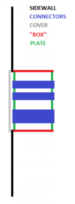
To avoid any misunderstanding: the cavity I am talkin about is the one in RED. I also had to remove the one in GREEN since it was partially overlapping with the cover
View attachment 16639