-
ORBITER-FORUM will be temporarily closed at 2026-07-23 18:00 UTC while we complete some OF maintenance tasks. The amount of downtime is expected to take up to one hour, but probably less.
You are using an out of date browser. It may not display this or other websites correctly.
You should upgrade or use an alternative browser.
You should upgrade or use an alternative browser.
Skylab 1973 rebuild
- Thread starter gattispilot
- Start date
Not sure either.
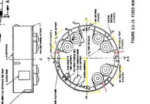
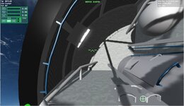
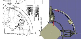
Two doors were provided in the FAS; one for access to the FAS interior and the AM EVA hatch during ground operations and the other for access to ground umbilical connectors. Four antennas; two deployable discones, and two UHF antennas were mounted on the FAS. The FAS structure also contained EVA support equipment as follows: egress handrails, work platform, film cassette tree supports, film transfer boom also called TEE, a TEE hook stowage box and lights. not sure about the inner circle. looks like grates? around the inside?
Two doors were provided in the FAS; one for access to the FAS interior and the AM EVA hatch during ground operations and the other for access to ground umbilical connectors. Four antennas; two deployable discones, and two UHF antennas were mounted on the FAS. The FAS structure also contained EVA support equipment as follows: egress handrails, work platform, film cassette tree supports, film transfer boom also called TEE, a TEE hook stowage box and lights. not sure about the inner circle. looks like grates? around the inside?
Attachments
- Joined
- Feb 6, 2008
- Messages
- 38,938
- Reaction score
- 3,937
- Points
- 203
- Location
- Wolfsburg
- Preferred Pronouns
- Sire
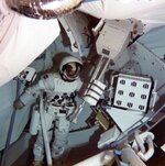
OK, in the photograph the AM support struts are indeed covered with textile, only the handrails (blue) stand out. I stand corrected there.
Now we get this:
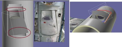
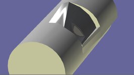
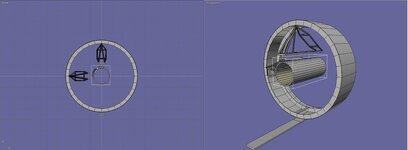
on the hatch I took a gemini hatch. I think because the Gemini is cone shape and the airlock tunnel is round. That elevate part is to make it fit.
But Nut sure if the front/back ends should be straight or curved
on the hatch I took a gemini hatch. I think because the Gemini is cone shape and the airlock tunnel is round. That elevate part is to make it fit.
But Nut sure if the front/back ends should be straight or curved
Attachments
- Joined
- Feb 6, 2008
- Messages
- 38,938
- Reaction score
- 3,937
- Points
- 203
- Location
- Wolfsburg
- Preferred Pronouns
- Sire
Yes, exactly. The hatch was used for pretending to save money, but installing the hatch into skylab was likely more expensive than building a new hatch. And both ends stay curved. the front end is likely best fitting the original curvature.
I will get the front end. Larger end to fit the curve and hinge end. And built the elevated part to match. But front and aft endwill be curved
- Joined
- Feb 6, 2008
- Messages
- 38,938
- Reaction score
- 3,937
- Points
- 203
- Location
- Wolfsburg
- Preferred Pronouns
- Sire
Just look at the photographs. The hatch is mostly white on the inside. On the outside, it seems to be a metal, it appears similar to the B-58 hull.
- Joined
- Feb 6, 2008
- Messages
- 38,938
- Reaction score
- 3,937
- Points
- 203
- Location
- Wolfsburg
- Preferred Pronouns
- Sire
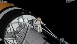
Well, your FAS structure needs some rework first, I would say. otherwise, I would place them just like in the drawings, because you can also see them in use in the rare EVA photographs.
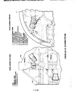
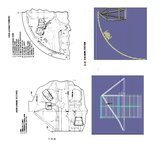
A cross section through the FAS structure is on page 102 of the Skylab Operations Handbook.
A cross section through the FAS structure is on page 102 of the Skylab Operations Handbook.
Last edited:
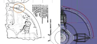
Thanks. What needs to be reworked?
I have the hand rail reversed. I think the platforms go on the red boxes.
I know there was extra EVA tools there. I guess I can attach them there. Ideally if we had a good mesh of an eva guy. They could grap the tools,.....
And I guess the restraints should be coded to be able to attach the guy.
I reversed the handrails. And put the foot restraints in the correct position.
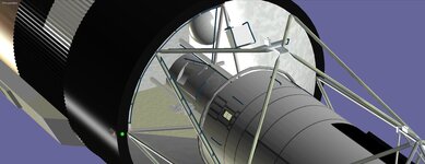
it looks like one of the platform is into the wall. everything else is attached to the inner ring?
I have the hand rail reversed. I think the platforms go on the red boxes.
I know there was extra EVA tools there. I guess I can attach them there. Ideally if we had a good mesh of an eva guy. They could grap the tools,.....
And I guess the restraints should be coded to be able to attach the guy.
I reversed the handrails. And put the foot restraints in the correct position.
it looks like one of the platform is into the wall. everything else is attached to the inner ring?
Attachments
Last edited:
- Joined
- Feb 6, 2008
- Messages
- 38,938
- Reaction score
- 3,937
- Points
- 203
- Location
- Wolfsburg
- Preferred Pronouns
- Sire
Thanks. What needs to be reworked?
The attachment of the AM support trusses is further inside, also there is hollow ring around the top of the FAS, stiffening the structure. Just look at the cross section on that page. This should also explain better how the EVA tools are placed there.
Thanks. Not seeing the hollow ring.
- Joined
- Feb 6, 2008
- Messages
- 38,938
- Reaction score
- 3,937
- Points
- 203
- Location
- Wolfsburg
- Preferred Pronouns
- Sire
Thanks. Not seeing the hollow ring.
Take a look at C-C, the rectangular part of that cross section. "Intercostal" means "Between two rips". Also the drawing in the center show pretty well, that oxygen tank attachments are installed on top of the intercostal surface.
2.0.9.3 SUBSYSTEMS AND MAJOR COMPONENT DESCRIPTIONS
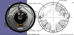
The FAS (figure 2.0.9-1) is a cylindrical structure, approximately 80 inches long and 260 inches in diameter,
consisting of thick skin and ring construction with local intercostals for structural backup of the ATM-DA
and the AM truss attach fitting.
The skin is constructed of four 90-degree sections of 0.45-inch thick 2024 T851 aluminum alloy. These sections
are spliced together and attached to three structural rings. The aft-most ring has a 5-inch width; the center
and forward-most rings have widths of 12 inches each. Web and intercostal arrangements are provided at each
of the splice joints, which occur at the Y and Z coordinates. The four AM trusses mount to the forward ring
of the FAS over the splice joints webs (figure 2.0.9-1). The six oxygen tanks are divided into pairs, equally
spaced between +Z and +Y, +Y and -Z, and -Z and -Y. The tanks are attached to the FAS structure through web
arrangements that fasten to the intercostal' mounts of the tanks.
Eight clevis fittings are provided on the forward ring for attachment of the DA lower truss. At points 45-
degrees off each side of the -Z coordinate, the inner discone antenna booms are mounted to the forward ring.
Webs are provided below each structural attach point for local strengthening.
- Joined
- Feb 6, 2008
- Messages
- 38,938
- Reaction score
- 3,937
- Points
- 203
- Location
- Wolfsburg
- Preferred Pronouns
- Sire
Also, in case you don't know it yet, "web" is the center part of an I beam or similar structures ("Steg" in German, the flange part is also called phonetically similar "Flansch" here), not more. At least I got pretty confused there, because it wasn't what I expected.
The attachment of the AM support trusses is further inside, also there is hollow ring around the top of the FAS, stiffening the structure. Just look at the cross section on that page. Thisp should also explain better how the EVA tools are placed there.
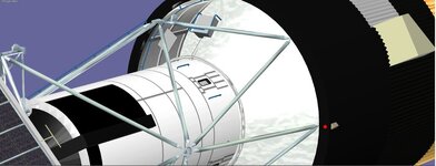
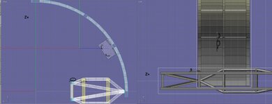
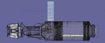
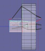
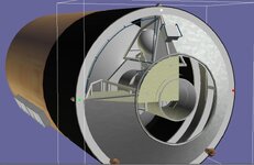
So I rebuilt the FAS with the 3 rings and parts of the 90 degree axis
I think the truss are too tall. They should be the height of the tunnel and attach at the top of the FAC My FAS is 2.03 meters tall. There is a 3ft tall Instrument unit between the FAS and OWS.
I wonder if the area open in the eva bay allowed you to see the dome of the workstation
I think the truss are too tall. They should be the height of the tunnel and attach at the top of the FAC My FAS is 2.03 meters tall. There is a 3ft tall Instrument unit between the FAS and OWS.
I wonder if the area open in the eva bay allowed you to see the dome of the workstation
Attachments

Last edited:
If at all possible (and this is just a humble request), would you be able to possibly make two versions of the Skylab?
Version 1 could be like Skylab as she flew, with version 2 being what she was supposed to look like (with the micrometeorite shielding and the missing solar array).
I remember watching Skylab launch and thinking something had gone horribly wrong when I'd later heard about the shielding being ripped away and NASA trying to figure out a fix. I wish I could have watched the EVA fix when Pete Conrad and Joe Kerwin cut that cable/strapping to free the solar "wing" (can you imagine the pucker factor of something that massive popping into place right in front of you?)