- Joined
- Feb 6, 2008
- Messages
- 38,938
- Reaction score
- 3,937
- Points
- 203
- Location
- Wolfsburg
- Preferred Pronouns
- Sire
Do you have that one already?
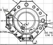
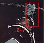
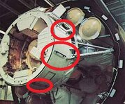
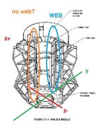
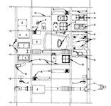
"Skylab Operations Handbook"
The drawings and the monochrome photos in that digitized manual are very good, they might help you a lot.
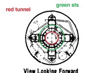
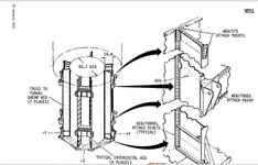
Page 101 has an excellent good drawing of the support structures you are fighting with.
"Skylab Operations Handbook"
The drawings and the monochrome photos in that digitized manual are very good, they might help you a lot.
Page 101 has an excellent good drawing of the support structures you are fighting with.