Thanks for everyone comments! Let me see if I can answer to everybody!
Questions:
- hidden RCS used for roll, pitch and yaw consumes fuel from main tank? (Vinka's hidden rcs seems not to use any fuel or huge ISP)
they are connected to the main tank but with huge Isp in order not to consume fuel, my guess is that also vinka did the same but I never checked.
Nice to have (medium):
- CrossSections are based on cylinder with Height and Diameter; but in many add-ons it's not taken in consideration the use of booster (actually I'm not sure that there is an add-on that takes this in consideration); is there any possibility that when are booster attached to add their CrossSections to main stage and at separation to use main stage default CrossSections?
It is already like that :thumbup:
I have to say that, compared to vinka, atmospheric flight is a bit different and I get a bit less drag. For this release I implemented the basic anyway which is consistent with Vinka's one (tested with two rockets side by side) and I'm leaving further improvements for future releases. Anyway side boosters are already added to the cross section!
Nice to have (low):
- RCS tank for RCS thrusters; no fuel remained -> no RCS available
- RCS ISP user defined (SpaceX use cold gas thrusters with only 70s specific impulse)
- ISP sea level user defined; you obtain ISP vacuum from BurnTime * Thrust / (FuelMass * 9.8066); instead of using ISP vacuum you could use an ISP based on ISP(sl) and ISP(vac)
I see this a bit differently: the fact that if fuel finishes no attitude control is possible seems to me consistent with the reality: for example for rockets with Thrust Vectoring if fuel is zero then attitude control is zero. And even for the others, since there is no translational RCS what would be the use of the RCS if the fuel of a stage is over?
At last: since user will define burn time and thrust, ISP will be a result of an exact calculation. If the user inputs ISP then burntime will be a result. The combination should be taken into account by the user in the definition of the burn time, so instead of defining and ISP based on ISP sl and ISP vac the burntime could take the difference in account. Anyway the input of ISP instead of burntime it's a proper point, but if I make a change of this kind retrocompatibility with old multistage2 configs will not be mantained. To be studied.
Hi fred18,I have a question,will you able to assign sound files to steps of the launch using the autopilot instead of a guidance file also?
For the time being no: only guidance steps with numerical parameters are accepted, no "disable(jettison)" or "playsound" can be added via the MFD at the moment. I'll see if it's easy to add them but I think it's not that easy.
Hi Fred.
Thank you for your very deep explanation of the inner workings of MS2015. As you can imagine it takes some time to grasp and comprehend so condensed information and what the implications are. So let me see if I understand it correct. The guidance computer separates the launch into three phases:
- Rollprogram (until desired roll >yaw; pitch values are obtained) then
- Open loop gravity turn (that ends when the trajectory intersects 35 KM alt) then
- PEG algorithm to the desired obit parameters.
So…
Roll program. I guess that’s quite “simple”. You calculate the desired track based on user requested inclination and thus obtain the heading and let the AP roll the vehicle until the actual hdg equals desired hdg . I guess you hold the picth close to vertical whilst rol program is running and keep yaw nulled at the same time.
the list is correct, the roll program not exactly: the guidance program always points a vector in space and keeps the roll nulled at the desired value. For MS2015 roll program the vehicle points the direction of launch azimuth and the pitch of the initial gravity turn using pitch and yaw and in the meantime rolls the vehicle upright or upside down depending on the mode desired.
Note: the desired attitude (upright or upside down) is obtained with the formula:
Code:
roll=0.5*(1-VinkaMode)*PI
which leads to 0 if VinkaMode is 1 and to PI if VinkaMode is -1. But it also leave the way open to particular interpretation, for example if you input mode -2 roll will be 3/2*PI and you'll fly the full flight banked 90* on a side!
Considering the
Open loop Gravity turn:
"All parameters"…Does this take into account boosters as well as early staging if that occurs prior to 35 KM alt…Or put in another way... Does the guidance computer operate a timeline of staging events during gravity turn or do you “assume” the thrust and mass (minus expended fuel off course :thumbup
")
is the same during gravity turn. I guess it is important to understand this if you need to “tweak” parameters.
You also write: and…
Does this mean that the gravity turn pitch attitude end state is determined only by the user inserted orbit parameters (PEA, APA) or is there an additional user parameter (s) whereby you tweak this pitch end state? I believe that the pitch state at PEG takeover is important in order to have a smooth pitch curve all the way up – else the PEG would have to pitch (violently?) up or down at take over time to meet desired orbital parameters.
Computational Evaluation of Gravity Turn takes into account the complete process of the rocket: booster jettison, fuel consumed etc. and it's built to determine the smallest pitch angle (plus 5% safety) that will lead the rocket to at least 35km.
I take the chance to anticipate the explanation of the "orbit" call parameters of the guidance program, so you will have a more clear vision. This is the structure of the call:
Time=orbit(PeA, ApA,target Inclination, Mode, Gravity Turn Initial Pitch, Target Abside)
example:
-10=orbit(180,220,-45,1,76,0)
the time is negative because calling this in a negative time can be used to set the initial countdown.
PeA=perigee altitude in km
ApA=apogee altitude in km
target inc=target inclination in degrees: - for launching southward, + for launching northward
Vinka Mode=1 for upright flight, -1 for upside down flight
Gravity turn initial pitch= the initial pitch with will give the start to the gravity turn
Target Abside= the target altitude at which we want to have the cutoff (useful for shuttle like vehicles, will explain why)
The only two absolutely mandatory parameters are target PeA and target ApA, for the rest if not specified a default will be assumed, let's see what:
-10=orbit(180,220)
will produce a launch with azimuth 90* and inclination obviously equal to launch latitude
VinkaMode will be 1 by default
Gravity turn initial pitch: the value calculated by the computational calculation will be used
target abside: if perigee is outside the atmosphere it will be used, otherwise the apogee will be used.
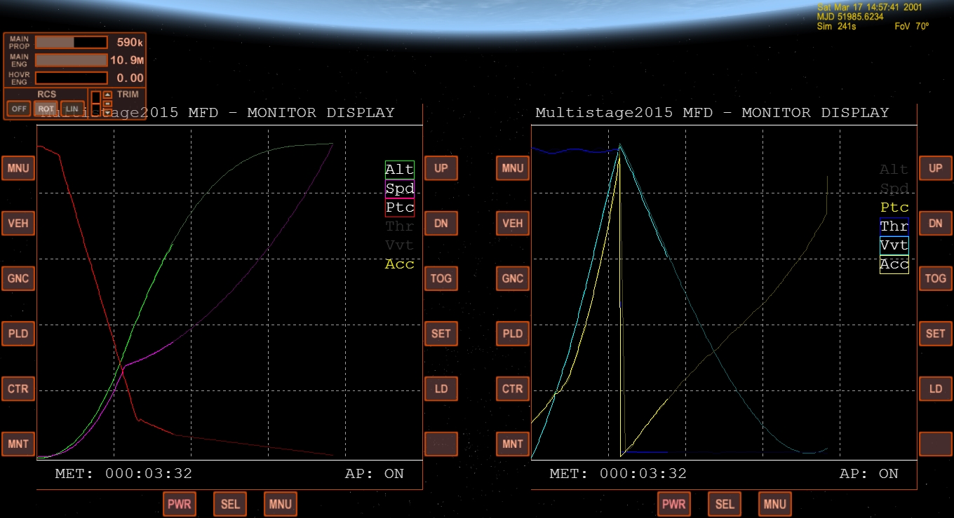
Please note that the calculated gravity turn initial pitch will be displayed as reference in both MFD and in orbiter.log file, so user will have a reference if the default value does not satisfy him.
Example: you want to launch to a low altitude orbit but the default Gravity Turn initial Pitch leads you to still have a high pitch at 35 km when the peg takes over and an abnormal pitch manouver takes place? then lower the value a bit for the next round until you see a smooth transition
Another Q and comment:
Do you somewhere in your stack have a computed value for the “time to orbit insertion” or “time to MECO” available prior to ignition can you display this in the MFD? Likewise based on this timing computation is it possible to calculate and display the propellant state of the final stage at MECO.
The Time to MECO would be very useful in relation to Launch MFD because you can use this to determine an optimal launch time to reach a desired LAN (Assuming that MS2015 does not take LAN into account – perhaps an idea for future expansion?).
For the propellant state it off course goes to either offload fuel or determine what is left of e TLI etc.
Predicted MECO is shown from the instant that PEG takes over in the MFD and in the HUD. I can add also a simple calculation to show it when still on ground.
Finally…IMHO one of the problems with almost all “launch auto pilots” (LaunchMFD, Velcro and MS”classic”) is if you have a weaker upper stage. Then you need to “aim higher” to allow for significant gravity loss until orbital velocity is reached – which might occur at a lower altitude than the highest point of the entire launch trajectory. Does the PEG allow for these type of trajectory. Today I always use Launch MFD but with multistaged vehicles (Current vehicle I use has three stages and a 4+2 boosters) I always use the manual pitch program(user define by table) and then go by trial and error until a satisfactory launch trajectory is obtained and thus repeatable. It still seems that MS2015 provide more advanced tool although some trial and error loop is still required (which is OK because you learn a lot from this:lol
.
Multistage PEG works and consider the real and current characteristics of the vehicle, therefore it aims higher from the beginning of the flight if the last stage is over. Since the alghorithm works for multistages vechicle there is basically no transition during staging, the guidance computer uses the best values taking already in consideration all the following stages parameters. It is done exactly to avoid hours of trials and error on pitch tables. The only trial and error can be the gravity turn initial pitch if the automatically computed value seems not satisfactory.
I hope to have given you a more clear vision of the points!
let me know if you need anything else
Cheers!

Fred


")