You are using an out of date browser. It may not display this or other websites correctly.
You should upgrade or use an alternative browser.
You should upgrade or use an alternative browser.
Centaur G/G Prime High Energy Upper Stage
- Thread starter DaveS
- Start date
- Joined
- Feb 6, 2008
- Messages
- 38,965
- Reaction score
- 3,937
- Points
- 203
- Location
- Wolfsburg
- Preferred Pronouns
- Sire
This video clearly shows something being exhausted through that duct:
The flow is too irregular for a gas generator exhaust. I would say its either the FCV valves (which should be fully closed during 100% operation and only open during start-up and shutdown) or a vent of the propellant utilization system.
What about this:
http://www.ulalaunch.com/uploads/do...Stages/TheCentaurUpperStageVehicleHistory.pdf
It mentions an Overboard vent system (OVS) developed specifically for that stage based on experiences with earlier Atlas-Centaur stages. Also the following news line: "The Lockheed Martin engineering team will take advantage of the delay to perform additional validation of interface loads on the duct of the Centaur upper stage's overboard vent system." Also the PDF mentions that the OVS also services a third FCV valve added in the RL-10A-4 engine, so it did likely not exist like that on the Centaur G family.
By the functions that this line has... I doubt it existed like that on the Shuttle-Centaur.
Last edited:

Did a little fast reading on the RL10 and my guess on the vent is either turbopump seal vent or gearbox vent.

I think that's enough reference for me. Probably on the weekend it'll be done.
I'll provide .3ds, texture pack and .msh for material reference. Or do you want .max file?
I'll provide .3ds, texture pack and .msh for material reference. Or do you want .max file?
- Joined
- Feb 4, 2008
- Messages
- 9,754
- Reaction score
- 1,026
- Points
- 203
I think that's enough reference for me. Probably on the weekend it'll be done.
I'll provide .3ds, texture pack and .msh for material reference. Or do you want .max file?
3ds is best as I have no way of opening max files.
- Joined
- Feb 4, 2008
- Messages
- 9,754
- Reaction score
- 1,026
- Points
- 203
Donamy: How's the EM wiring texture coming along? I'm also in need of a new radiation shield(this is the reflective foil covering the two propellant tanks) texture. I need it to be similar to the one shown on the Centaur G Prime on the right in this photo. It is of two Titan IV Centaur G Primes during processing at the Cape.
The stage on the left shows the foam insulation that covers the LH2 tank only and is underneath the radiation shield. It also shows the EM wiring running along the length of the LH2 tank down to a "cableway box" located on the brown/reddish Purge Plenum between the LH2 tank transition cone and the LOX tank cylinder.
From there it runs to through two busing panels located on either side of the LH2 engine feedline on the LOX tank cylinder down to two staging disconnect panels located at the very aft end of the Aft Adapter. Each disconnect panel has three connectors that mates with similar disconnect panels on the launcher end (Titan in this case, for shuttle it would have been the CISS Deployment Adapter). While the wiring on the LH2 tank was covered by the radiation shield, the wiring on the LOX tank would have been fully exposed and visible. Also, the top "cableway box" would not have been present on the S/C version. In its place was a disconnect panel located on the EM itself.

---------- Post added 01-29-15 at 12:13 AM ---------- Previous post was 01-28-15 at 11:13 PM ----------
Latest Centaur G Prime work:

---------- Post added at 04:29 AM ---------- Previous post was at 12:13 AM ----------
I'm still looking for these two items. Once they have been added to the actual code, it won't be difficult for me to update them once the new meshes are available.
The stage on the left shows the foam insulation that covers the LH2 tank only and is underneath the radiation shield. It also shows the EM wiring running along the length of the LH2 tank down to a "cableway box" located on the brown/reddish Purge Plenum between the LH2 tank transition cone and the LOX tank cylinder.
From there it runs to through two busing panels located on either side of the LH2 engine feedline on the LOX tank cylinder down to two staging disconnect panels located at the very aft end of the Aft Adapter. Each disconnect panel has three connectors that mates with similar disconnect panels on the launcher end (Titan in this case, for shuttle it would have been the CISS Deployment Adapter). While the wiring on the LH2 tank was covered by the radiation shield, the wiring on the LOX tank would have been fully exposed and visible. Also, the top "cableway box" would not have been present on the S/C version. In its place was a disconnect panel located on the EM itself.
---------- Post added 01-29-15 at 12:13 AM ---------- Previous post was 01-28-15 at 11:13 PM ----------
Latest Centaur G Prime work:
---------- Post added at 04:29 AM ---------- Previous post was at 12:13 AM ----------
One thing I noticed on the CISS is that the Deployment Adapter rotation links and arms isn't animated. These arms and links are connected to the actual PDUs that rotate the Deployment Adapter. The arms rotate CCW
I looked at the CISS source code and noticed the animations for the actual propellant ducts is commented out. What is the reason why they're commented out?
I'm still looking for these two items. Once they have been added to the actual code, it won't be difficult for me to update them once the new meshes are available.
I added some cabling seen in reference photos and have few more questions.
Apart from the top of turbopump assembly, I need to figure out yet, do we need any more details (note that cooling tubes and nozzle bands will be done by normal map)???
Next question - should I make texture with ambient occlusion shadows baked in? If so should I simulate in it placement in the botom of centaur stage? In that case top of the engine will be darker than bottom.
Last edited:
- Joined
- Feb 4, 2008
- Messages
- 9,754
- Reaction score
- 1,026
- Points
- 203
I think AO maps is best left out for now, unless you can make them even as theirs no real way to make the shadows dynamic and dependent on the actual solar-relative attitude. Also, the top xducer box inboard side should more closely follow the actual shape of the nozzle as this enlarged photo shows. Right now it looks like it's just barely hanging on.

I think AO maps is best left out for now, unless you can make them even as theirs no real way to make the shadows dynamic and dependent on the actual solar-relative attitude. Also, the top xducer box inboard side should more closely follow the actual shape of the nozzle as this enlarged photo shows. Right now it looks like it's just barely hanging on.
Do you think angled one looks better?


- Joined
- Feb 4, 2008
- Messages
- 9,754
- Reaction score
- 1,026
- Points
- 203
That's it. To me it looks like it is part of the actual nozzle structure.On the photo you had different transducer box (this with chamfered walls)
Ok - fixed
- Joined
- Feb 4, 2008
- Messages
- 9,754
- Reaction score
- 1,026
- Points
- 203
That cut-out in the outboard side is most likely a section that has been removed for display purposes. There other obvious non-flight cut-outs like that on the rest of the engine as well like on the MCC and the actual nozzle which would compromise the actual combustion as well as nozzle cooling and efficiency.I think he meant something more like this.
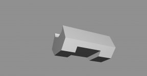
gold - UVW unwrapped, black - to unwrap.

---------- Post added at 01:58 AM ---------- Previous post was at 12:18 AM ----------
Some minor elements left to unwrap but it's 1 am and I can't make more today.
I'm pretty satisfied with progress today.

---------- Post added at 01:58 AM ---------- Previous post was at 12:18 AM ----------
Some minor elements left to unwrap but it's 1 am and I can't make more today.
I'm pretty satisfied with progress today.
Similar threads
- Replies
- 10
- Views
- 4K
- Replies
- 21
- Views
- 18K
- Replies
- 1
- Views
- 9K
- Replies
- 13
- Views
- 6K