Project Space Shuttle Vessel

I meant the launch time itself, in the Launch tab. Don't lose sleep over a 1s difference in launch time, as Orbiter is not using UTC, so there is already a difference of 50s or so in the 1980s.
BTW: could you post the (troublesome) launch time you input into ME, so I can then confirm this issue gets fixed?

For now (v1.8) I'll change the LCC so there is less chance, or hopefully none, of falling into this hole again. Eventually (v2.0) I'll change the start time to T-40s or so (somewhere where no commands are issued) to avoid this entirely.

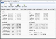
Ah ok I just tried setting the launch time on the Launch tab to 12:02:59 instead of 12:03:00 (the troublesome time) and it fixes the issue. Here is the json file with the unmodified launch time:

 
  • Like
Reactions: GLS
I think there's something wrong with the RCS currently. I have to deflect my joystick (X52) quite a lot to get any sort of response from the RCS. I have checked with SPEC 43 CONTROLLERS in OPS8 and I am getting the appropriate controller response that I expect, so it looks like there's something odd going on with controller/RCS connection.
 
there's something wrong with the RCS currently
Only something? :ROFLMAO: That is why I'm reworking all of that.
This problem seems to be more related to the OrbitDAP (which should also see some improvements as it will have to adapt to the new RCS). Maybe the RHC deadbands are wrong, and the "no fire area" is larger than it should be, or maybe that is OK and it is just the way it works, as the vehicle was usually turned by the DAP and slowly.
Turning it slowly is what I am trying to do, but due to the deadzone it is pvery difficult to establish and maintain <2°/s rate as you end up overshooting it and up with a 3°/s or more rate. It is good to read that this will be taken care of. On the same subject, I have found that a 2.0 value for RHCRate in SSV_OV.cfg is a pretty good value for a proper RHC response rate simulation through the keyboard.
 
Hi, GLS, Why does the Crawler Transporter could not stop at the point of the docking height (3 feet), and could not attaching to the MLP ? Another quest is if you can make the track animation of the Crawler Transporter ?
 
Hi, GLS, Why does the Crawler Transporter could not stop at the point of the docking height (3 feet), and could not attaching to the MLP ?
Hi there!
It should stop where it needs... probably not 3 feet exactly. As for the attachment, you need to really be in the correct place... which is not simple. The LDS helps you to align both ends of the CT to the MLP, thus you only need to stop (longitudinally) at the right place, which currently has to be done visually.


Another quest is if you can make the track animation of the Crawler Transporter ?
I could but it would take a LONG time, so the effort/reward ratio isn't that good. I remember there are a few pistons "on the inside" that are not animated, and should be easy to do, but I haven't got to them yet.
 
Thanks for your reply, but I tried many times ,I think I couldn't do that . Could you give a scenarios file to show the state of the CT succeeds docking to the MLP ?
 
The alignment of the Crawler is done through the use both the Laser Docking System (LDS) and ground observers stationed outside the Crawler that are in communication with the LDS operator in the Crawler Engineer Control Room who is also in communication with the operators in the driver cabs. The observers are the main source for the alignment with the LDS acting as back-up/verification of lateral alignment only. Longitudinal alignment comes from the observers.

The first attached screenshot is from the coverage of the second STS-114 rollout to pad B on June 14 2005 and shows one of the observers manning the #3 MLP Mount Mechanism basket aiding in alignment of the Crawler/MLP docking. Second screenshot shows the Engineer Control Room with the LDS Engineer station outlined in red.

The alignment communications could be accomplished through the use of since long deactivated but still present comms system code in the main orbiter vehicle code.
 

Attachments

  • STS114_observer_MLP_mount.jpg
    STS114_observer_MLP_mount.jpg
    79.8 KB · Views: 10
  • Crawler_LDS_station.jpg
    Crawler_LDS_station.jpg
    68.7 KB · Views: 11
I think that GLS's Crawler Transporter mod is much better than allof the others, I expect to see the CT jacking the space shuttle to move , but it is too difficult to do that .
 
I think that GLS's Crawler Transporter mod is much better than allof the others, I expect to see the CT jacking the space shuttle to move , but it is too difficult to do that .
Try the "MLP roll-off" scenario, go up the pad slowly and check the LDS as you move left and right, to get the gray bar centered. The 2 modes you need are the G CIRC, which turns the CT left of right, and the CRAB mode which basically shifts the CT to the side, without turning it, so keeping the orientation to a target.
It is not easy, and the fact that the CT is slow on everything it does, makes it even harder, but practice makes perfect.

Does anyone have the IUS deployment checklist, I looked everywhere and in the manual the section is blank.
The STS-93 IUS Deploy Checklist should be available somewhere on the internet... but lots of switches don't work yet, so maybe I should make a simple checklist.
The highlights are:
  • Release PRLAs on panel A6
  • Tilt Table Actuator Drive Enable Pri 1 - Intermediate
  • Tilt Table Actuator Motion Pri 1 - Raise
(table motion to 29º)
  • Umbilicals Pri - Enable
  • Umbilicals Pri - Release
  • Tilt Table Actuator Motion Pri 1 - Raise
(table motion to 58º?)
  • Pyro Bus Pri - On
  • IUS Deployment Pri - Enable
  • IUS Deployment Pri - Deploy
(wait a few seconds until it is well above the vehicle, do a few -X RCS pulses, and wave as it passes overhead)
  • Tilt Table Actuator Drive Enable Pri 1 - Maximum
  • Tilt Table Actuator Motion Pri 1 - Lower
(table motion to -6º?)
 
Hi ,GLS , I have tried to use scneditor to get the gray bar centered ,but I don't know where is the correct point of the foward or behind . and another problem is that I couldn't control the jacking to stop ,it always auto stop at 2.91 feet ,so I couldn't know if this is the correct point of the docking height?
 
Hi ,GLS , I have tried to use scneditor to get the gray bar centered ,but I don't know where is the correct point of the foward or behind
If I remember correctly, Cab 3 is the one towards the pads, and Cab 1 is towards the VAB. There is a switch in the LDS display that controls which position it shows, so you don't have to change cabs. With that you can see where each end is in relation to the target. For fine lateral control, putting the Mode push button in +-2º, is very useful as it cuts the steering commands by a third.
Again, patience is required.

and another problem is that I couldn't control the jacking to stop ,it always auto stop at 2.91 feet ,so I couldn't know if this is the correct point of the docking height?
It should be that 2.91 position. Currently the jacking is controlled by switching between pre-defined target positions, which be all the needed positions.
 
The mods are wonderful, and I expect to see the track animation ,if you agree, I think you can correct the manual :the docking height is 2.41 feet. and the four circular marking at the top of the CT's four corner must alignment at the four short boss at the bottom of the MLP .
 
I am trying to figure out the Mission Editor.
Not sure why is compressed where the numbers are hard to read. I am sure my pc settings?

But for STS-5 there are 2 ASE,.... I used scenario editor and attachment manager to get one in place.
ASE:SSV_ASE1 DOOR 1 1.0000 PL1_OFS 0.0000 -2.5 0.0000 PL1_DIR 0.0000 1.0000 0.0000 PL1_ROT 0.0000 0.0000 1.0000 STATUS Orbiting Earth RPOS 377031.770 -2219185.042 6137211.672 RVEL -6913.4559 3338.0463 1630.6629 AROT -121.908 -62.272 13.496 VROT -0.0040 -0.0050 0.0061 ATTACHED 0:12,Columbia AFCMODE 7 NAVFREQ 0 0 XPDR 0 END
 

Attachments

  • ssvsts5setup.jpg
    ssvsts5setup.jpg
    51.7 KB · Views: 19
  • ssvsetting.jpg
    ssvsetting.jpg
    99.9 KB · Views: 19
  • ssvase4.jpg
    ssvase4.jpg
    95.4 KB · Views: 19
Not sure why is compressed where the numbers are hard to read. I am sure my pc settings?
Wow... never seen that... what is you resolution?

But for STS-5 there are 2 ASE,.... I used scenario editor and attachment manager to get one in place.
Something like this should work:
ASEs -> Passive Payload: define PLIDs as needed (PLB photos should help in finding the actual locations), and set vessel-specific parameters (DOOR, etc)
PAMs -> Other vessels: set vessel-specific parameters and DOCK parameter to respective ASE
SBS/TELESAT -> Other vessels: set vessel-specific parameters and DOCK parameter to respective PAM


Eventually this will be as easy as adding a payload to the IUS or Centaur, but I have other things to do first. 🤷‍♂️
 
Wow... never seen that... what is you resolution?


Something like this should work:
ASEs -> Passive Payload: define PLIDs as needed (PLB photos should help in finding the actual locations), and set vessel-specific parameters (DOOR, etc)
PAMs -> Other vessels: set vessel-specific parameters and DOCK parameter to respective ASE
SBS/TELESAT -> Other vessels: set vessel-specific parameters and DOCK parameter to respective PAM


Eventually this will be as easy as adding a payload to the IUS or Centaur, but I have other things to do first. 🤷‍♂️
Resolution of computer display? I will check

Everything else looks ok

For ASEs for STS-5 they are in bay 6 and 8
For me I use the old STS code and use attachments. So the satellite is attached to the PAM.


So it sounds like I should be able to add the ASE in the mission editor and assign it to bay 6, right
 
I installed my Orbiter again and after everything was installed according to the manual this is happening.

Some help ?
All scenarios? The log shows a DG loading, but the image has Atlantis...


So it sounds like I should be able to add the ASE in the mission editor and assign it to bay 6, right
Nope, it should be a Passive Payload. Just set the PLIDs (the attachment should be the keel trunnion), and the latches and bridges will show up where they should.
 
Only SSV scenarios.
It was working normally in version 1.7, after I reinstalled my orbiter this is happening, I tried installing older versions and still the problem persists.
I need a log of that, please.
 
Back
Top