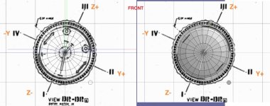
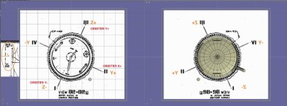
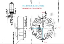
Skylab 1973 rebuild

Thanks. Yes once I get my brain straight on the interior of the OWS, it will be good. The ATM and airlock are straight x,y. while the OWS is about 20 degrees off center.

Once I get it working. I can add another panel which was removed. I will add an attachment for the MMU.
 
Skylab came and went with out much fan fair and until the ISS it might have been the most important program NASA did. thanks for working to bring this alive in 2016.

Not a miracle 😅 
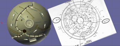
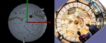
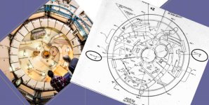
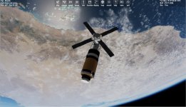
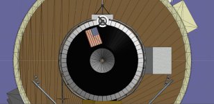
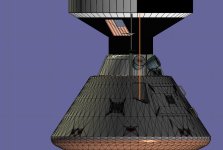
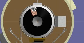
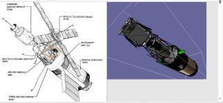
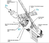
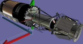
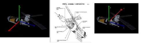
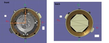
Although the OWS provided a lot of space, there was also a lot of different equipment/stuff installed. And the arrangement was strange here and there I think. But they did the best to utilize the leftovers of Apollo. I like that grid-design of the floor and ceiling of the crew compartment by the way. That "bike shoe" locking mechanism certainly was nice. Also the dining table was actually more advanced than that messy "picnic table" onboard ISS imho. Although today the space food system is way better.

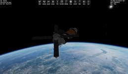
I'm glad you do the Skylab for Orbiter :hailprobe: I fear we'll never get such an accurate simulation of it again. And it's actually sad the program didn't get that much attention in the 1970s, except its orbital demise in 1979. Without the internet, there wouldn't even be a lot of detailed information.
 
Skylab came and went with out much fan fair and until the ISS it might have been the most important program NASA did. thanks for working to bring this alive in 2016.
Yeah. Scientifically it offered more capabilities than Mercury, Gemini and Apollo altogether I think. It gets beaten by the ISS in that department. But Skylab certainly still remains the best place in terms of available space inside a space station. Must have been an awesome sight when you float from the airlock module "down" into the orbital workshop :cool:


Ok lots of drawings. In the drawing they mark the Z and Y in orbiter they are Y and X. Some drawing use I,II,III,IV. I started at the top of the OWS. which is view BR. BR is just on top of the hatch looking back. I then took my hatch and placed the BR view on it. In some views I had to move the drawing back(AFT) so you could see the mesh.
But you can see the issue if you look from the front the angles of the X and Y change. But if we look from the front and look back. we see the hatch is wrong it is 130 degrees out. And the y+ is at 1-2 o'clock.

Deck 1. using the same technique. You can see one of the emergency exit is correct.

I think this is correct? but I will base the OWS structures off the drawings. And then when finished rotate 24 degrees counter clock wise so as to align the x and Y axis.

The 2 Science air locks are along the y axis. The one on top is where the parasol comes out of.
 

Attachments

  • brview.jpg
    brview.jpg
    35.3 KB · Views: 5
  • FLOORBB1.jpg
    FLOORBB1.jpg
    87.2 KB · Views: 5
  • floorbb.jpg
    floorbb.jpg
    126.8 KB · Views: 5
  • FLOORBB2.jpg
    FLOORBB2.jpg
    100.9 KB · Views: 5
  • direction.jpg
    direction.jpg
    53 KB · Views: 6
  • BRVIEW4.jpg
    BRVIEW4.jpg
    58.7 KB · Views: 6
  • BRVIEW3.jpg
    BRVIEW3.jpg
    66.8 KB · Views: 6
  • BRVIEW2.jpg
    BRVIEW2.jpg
    58.1 KB · Views: 6
  • BRVIEW1.jpg
    BRVIEW1.jpg
    19.2 KB · Views: 5
Brain still hurting. But it seems that in the nasa drawing z is y x is z. So in the drawing X+ is forward Z+ up is Z+.

BUT the Y in the nasa drawing is X in orbiter. and it seems that Y+ in the nasa drawing should be X- in orbiter and model.
In the drawings the eva hatch is -Z and +y But I think in the model it is +Z and +X . I think it needs to be +Y/+Z nasa to allow the guys to get to the film

This is what I need confirmed. I think the x/y nasa are reversed of the model/orbiter?
 

Attachments

  • ORINT7.jpg
    ORINT7.jpg
    88.7 KB · Views: 6
  • ORIENT7.jpg
    ORIENT7.jpg
    71.8 KB · Views: 7
  • ORIENT3.jpg
    ORIENT3.jpg
    77 KB · Views: 8
  • ORIENT2.jpg
    ORIENT2.jpg
    48.9 KB · Views: 8
  • NEWOWSHATCH.jpg
    NEWOWSHATCH.jpg
    58.9 KB · Views: 8
  • EVABAYLOCATION.jpg
    EVABAYLOCATION.jpg
    115.8 KB · Views: 7
  • dome1.jpg
    dome1.jpg
    97 KB · Views: 7
This is what I need confirmed. I think the x/y nasa are reversed of the model/orbiter?

Of course. Don't you yet know it?

Orbiter uses the old Direct3D coordinate system of Microsoft: Left-handed, Z+ points forward.
Each NASA project uses one or more coordinate systems, but to avoid headaches, there are some common conventions: They are right-handed, the X axis usually points in the most important direction, forward or towards the object that should be observed.

So, you ALWAYS have to pay attention, which coordinate system is used there. If you are not sure, assume body coordinates. And you must convert them into Orbiter. But for that, you can use Excel or, if you want more comfort and reusability, write your own custom tool for that.

 
Thanks.

SO in nasa we get 12 Z+ 3 X- 6 Z- and 9 x+ BUt for the model and orbiter we should use 12 Y+ 3 x+ and 6 Y- and 9 x-
?

So looking from the front and the top is Y+ in model and orbiter. The eva bay is on the -x and +Y side. on a clock 9-12, right

But on the drawing it has it at +Y and -z .


So in the model and in orbiter it is +Y ,-X


But since in both left and right hand Z is UP. Should I rotate skylab so that Z is up and not forward?
 

Attachments

  • left.righthand.jpg
    left.righthand.jpg
    119.4 KB · Views: 2
  • ORINT7.jpg
    ORINT7.jpg
    96.7 KB · Views: 2
  • BRVIEW3.jpg
    BRVIEW3.jpg
    71.8 KB · Views: 2
  • airlockeva.jpg
    airlockeva.jpg
    70.2 KB · Views: 2
Last edited:
So which way is UP. I thought Z+ was up and Z- down.

But here the mda Z- is up and Z+ down.
 

Attachments

  • mdadirection.jpg
    mdadirection.jpg
    81.8 KB · Views: 3
I just need to know the orientation. So Orbiter and mesh? uses left hand while NASA uses right hand, correct?

I am confused. It seems the Z+ maybe the bottom and z- the top? As the eva is +Y and-Z the mda bottom faces +Z but the eva bay needs to be at the top so to get access to the film.

Here is why it matters on the drawing of the upper deck because it is offset. the whole interior/escape hatch,.... changes. The model side is a mirror of the nasa side. Is this correct?
 

Attachments

  • brview6.jpg
    brview6.jpg
    47 KB · Views: 5
  • nasaskylaborint.jpg
    nasaskylaborint.jpg
    38.3 KB · Views: 5
  • nasaskylaborint1.jpg
    nasaskylaborint1.jpg
    59.5 KB · Views: 6
  • floor1A.jpg
    floor1A.jpg
    96.8 KB · Views: 5
Last edited:
OK. I think I am getting closer. The issue is the MDA/airlock are based off of straight x,y axis. While the OWS is off set.

on the model looking from the front to the Aft. Y+(nasa) is at 9oclock. That makes it -x in the model.

Here to get it to fit with the mda I can either build as is. Or rotate the image to align which is about 20 degrees and build the mesh. If I build as is the whole OWS will need to rotate.

Also if I ever get this done. I was looking at the so called Skylab 1980. I did notice in the Skylab1973 code was the wing fold for power module. That was for the power module and shuttle docking.
 

Attachments

  • doommodel3.jpg
    doommodel3.jpg
    82.2 KB · Views: 4
  • doommodel1.jpg
    doommodel1.jpg
    87.8 KB · Views: 4
Here's some of Skylab's TLE data retrieved from CelesTrak:
I've converted Skylab's TLE data to scenario parameters readable by Orbiter. The dates represent some of the significant events during the station's operational lifetime
 

Attachments

I thought I had but looking at real photo I didn't.

I think I had the interior 180 degrees off.

So I rotate the mesh 180 and loaded into vessel builder and now we get this. It matches the images.

I took the real view and put the drawing with it and matched it. And the rotated it so z is up/down.

After rotating the dome stuff 180 degrees it matches the image:)
 

Attachments

  • doomview5.jpg
    doomview5.jpg
    67.3 KB · Views: 2
  • domeview8.jpg
    domeview8.jpg
    64.8 KB · Views: 2
  • domeview9.jpg
    domeview9.jpg
    101.8 KB · Views: 2
If the dome is correct we get this. Z+ is position III.

Carry that to the floors deck 1 looks good. Science airlock are solar side/non solar side. The SAL with the tripod is where the parasol comes out of.

So if the solar side is +Z then this is good.

The problem then is deck 2. Using the same images. now the window is in position III z+.

Any ideas?

So the window is on the bottom part not facing the parasol. So it seems the lower deck is Z+ III is now down?
 

Attachments

  • windowlocation.jpg
    windowlocation.jpg
    125.2 KB · Views: 6
  • floor2view.jpg
    floor2view.jpg
    138.4 KB · Views: 5
  • floor1view.jpg
    floor1view.jpg
    105.5 KB · Views: 6
  • skylabdirection1.jpg
    skylabdirection1.jpg
    65.1 KB · Views: 7
  • skylabwindowlocation.jpg
    skylabwindowlocation.jpg
    62.7 KB · Views: 7
Last edited:
Close to another release. Things I added are the ows and STL windows has covers. I redid the docking target.

BUT not sure if the position is good.

The Apollo is AMSO. But it seems I should be able to look and see the alignment

CreateDock(_V(0, 0, +10.26), _V(0, 0, 1), _V(-0.707107, 0.707107, 0));

Here I added an AAPO CSM and aligned the dock. I think the target should be aligned with the orange line?
 

Attachments

  • skylabdock1.jpg
    skylabdock1.jpg
    48.3 KB · Views: 14
  • skylabdock2.jpg
    skylabdock2.jpg
    58.4 KB · Views: 15
  • skylaborbit2.jpg
    skylaborbit2.jpg
    64.4 KB · Views: 16
  • skylaborbit1.jpg
    skylaborbit1.jpg
    92.6 KB · Views: 18
  • skylabdock3.jpg
    skylabdock3.jpg
    82.2 KB · Views: 14
  • SKYLABDOCK4.jpg
    SKYLABDOCK4.jpg
    77.5 KB · Views: 12
Last edited:
2.0.7.3.3 Docking Alignment TargetsDocking alignment targets provide the CSM crew with visual cues for controlling precontact alignment and position.The docking al ignment targets are of the Apollo LM type and are mounted on the MDA at each CSM docking port.The target base and stand-off cross are painted with "Day Glo" paint, and include self-illuminating devices or attachments. The docking alignment target for the principal port, the axial port, is located 46 inches fromthe port, center to center, and is 75 degrees from the -Y axis toward the -Z axis.The target consists of an inner circle and standoff cross of black with self-illuminating discs within an outercircumference of white (figures 2.0.7-8 and 2.0.7-1). The target-base diameter is 17.68 inches. The standoff cross is centered 11 inches higher than the base and, as seen at the intercept, is parallel to the X-axis andperpendicular to the Y-axis and the Z-axis.2.0.7.3.4 Docking Ports and MechanismsThe MDA has 2 docking ports. The axial docking port, which is the prime docking port, is located at the forwardend of the MDA and centered about the X-axis. The radial (secondary) docking port is located 103 inches forwardof the MDA/AM interface on the -Z axis.Both the axial and the radial docking ports have standard Apollo drogues and docking rings to permit CSM docking.The radial docking port, however, does not have provisions for the transfer of electrical power, communications,and conditioned air. The components that make up the MDA port are the tunnel structure, the drogue, and pressurehatches.

The Docking target is 15 degrees off center (90-75). and 46 inches off center. We get this. But now I think the flag is wrong? I found a image of Skylab front In my drawing the target is around 5 degrees.
Looks right but is it?

Not sure where the target should be??
 

Attachments

  • skylabdock5.jpg
    skylabdock5.jpg
    44.1 KB · Views: 11
  • mdamountedtarget.jpg
    mdamountedtarget.jpg
    64.2 KB · Views: 12
  • skylabflag2.jpg
    skylabflag2.jpg
    89.5 KB · Views: 14
  • skylabflag1.jpg
    skylabflag1.jpg
    19.5 KB · Views: 14
  • amsotarget.jpg
    amsotarget.jpg
    61.8 KB · Views: 12
Last edited:
The docking target must always be aligned with the crosshair mounted on the station (similar to how Apollo astronauts guide their craft on docking with their lunar modules)
 
Here is the new meshes,.....

Keys:
1,2,3 change CMG mode
7,8,9 enter pitch roll and yaw target

K solar array
0 (zero) parasol
G ATM
5 twin shade
ALT & 1 inner airlock
ALT & 2 outer airlock
ALT & 4 OWS window cover
ALT & 5 STL window cover
6 OWS hatch
CTRL and Space opens windows

Thanks for all the help. @Gargantua2024 for the scenarios

get it here: https://u.pcloud.link/publink/show?code=XZICdO0ZlaGDIGEYd0Lkr0fBW8AWJVv5JnuV

It is not letting me load on the forum for some reason

I forgot a cfg. It is in the 9.3.1zip.zip file
 

Attachments

  • skylaborbit1.jpg
    skylaborbit1.jpg
    92.6 KB · Views: 8
  • skylaborbit2.jpg
    skylaborbit2.jpg
    64.4 KB · Views: 8
  • skylabnew9.3.1zip.zip
    skylabnew9.3.1zip.zip
    300 bytes · Views: 8
Last edited:
For historical context that I forgot to apply in the scenarios I gave:
  • The parasol sunshield was unfurled on May 26th
  • The main solar array wasn't fully extended until June 7th when Pete Conrad removed the metal strap that jammed it during launch on May 14th
  • The twin-pole sunshade was installed on the station via EVA on August 6th
 
Thanks. I can update them.

As far a actual launch. I can use AMSO for 2016. But not sure what the orbit should be for release. I have the docking ports open but since no apollo has crew transfer and no apollo can open the hatch. We can keep it as is.

I can make the same model but with 2 solar arrays as planned.

If needed the 1979/80 Skylab refit for the shuttle.,.....

As far as releases I wonder about licenses,,,, I will credit the orginal 1973 skylab and the code from ISS_HD which gives the floating crew, VC movement, and CMG
 
Last edited:
Back
Top