Project Launch MFD development thread

uuh, the link to the 2010 compile of the beta is broken.

---------- Post added at 02:40 PM ---------- Previous post was at 02:38 PM ----------

oh, never mind. It was google chrome having problems with my DNS.
 
I've improved the autopilot. Now it will bank the ship to make it use lift to reach PEG mark by itself.

I've also been playing with XR family, and here's the good news: Now there's a possibility to use the autopilot while using scram engines, ie. using the AP only for azimuth correction, while leaving the pitch control to the pilot. You can do it by pressing DEF button in the Standard mode, so that the pitch readout is canceled and then pressing the AP button.

Please test while I prepare the release :)

http://www.elwico.pl/~ender-sz/orbiter-pdf/pliki/LaunchMFD.dll.zip
 
Looks good, time to create another Orbiter installation for XR vessels and try it. Azimuth was never a big problem for me, but it could reduce fuel waste caused by plane changes.
 
Time to launch explaination

The weather is bad today so I thought I'd explain the principle of new time to launch calculation and why I needed help in my Space math thread.

When you are landed, the launch window should be calculated as in the attached screenshot, ie. not by calculating time to orbits' intersection, covered with current orbital velocity ( < rotation @ equator), as it was correctly calculated when in flight, but by calculating the shown distance covered with velocity at equator (satellite's plane velocity)

[EDIT]
Which has just enlightened me that the former, incorrect assumption, was a reason for errors in Direct Ascent :)
 

Attachments

  • time-to-launch.png
    time-to-launch.png
    51.3 KB · Views: 23
Last edited:
Below is a video tutorial how to use the direct ascent program (11 minutes). The latest changes of the program are:
- greatly improved CPU usage. Solutions are found in less than 40 iterations for an accuracy of 1 km
- optimal velocity solver! - theoretically helps saving fuel (you should use unlimited fuel for now)
- improved accuracy of all phases except the turning phase

To do (in the order of addressing):
- 3D turning phase finally
- support for limited fuel
- ability to target satellites flying high (3D insertion path)


Technical (math) explanations will follow. I need to prepare them for my M.Sc. anyway.

The beta dll can be downloaded from below:
http://www.elwico.pl/~ender-sz/orbiter-pdf/pliki/LaunchMFD.dll.zip
 
Nice job!

Tho the way you fly that shuttle you are almost better off flying directly at the thing and doing a huge burn to equalize with ISS. Star Trek style
 
Nice job!

Tho the way you fly that shuttle you are almost better off flying directly at the thing and doing a huge burn to equalize with ISS. Star Trek style

My optimal velocity solver tells me something different :)
I believe that the way I fly is the best thing that you can do - first I try to reach the appropriate position slightly before the sat's plane, using the shortest possible path. I don't accelerate to full speed because turning / equalizing also takes a lot of fuel. I will share my optimal velocity solver, maybe during next weekend, and you'll see. It's a bit complicated, therefore requires some explanations.

For now, I'd like to show the newest incarnation of the direct ascent solver, containing 3D turning phase. It's never looked so smooth :)

http://www.elwico.pl/~ender-sz/orbiter-pdf/pliki/LaunchMFD-da-solver.zip

The grey great circle that you'll notice is the starting position. This way you can observe how much you needed to wait before launch. The slider below the graph lets you simulate time change before launch, as if you were waiting longer/shorter for given parameters.

The 3D turning phase is done by getting 3D ship's position and vectors, projecting the velocity onto a plane, rotating along the ship's position + 90 degrees, so it's always perpendicular to the ship's velocity. It's as if you were watching the ship's velocity from 3D Map MFD, from the equator, but always having the ship in the middle on the oY axis. Then the velocity is flat. To this velocity I add a 2D velocity calculated by the usual azimuth calculation functions, convert the sum back to 3D space and add it to 3D position, thus properly updating it in 3D :)

As they say, a piece of code is worth a thousand of words, so here it goes. Some things may be hard to understand, but the most important part is the 2D projection.

Code:
void DirectAscent::inner_loop()
{
  double sshx_before_inner = sshx;
  sphShipPos.r = target_radius;

  bool b3D = true;
  double velModule;
  Spherical localsphShipPos;
  Vect3 localShPos;
  Vect3 localShVel;
  double magMulPos;

  {
    velModule = max_xvel;
    localsphShipPos = sphShipPos;
    localsphShipPos.theta += PI/2;
    localShPos = ConvertSpherical2Cartesian( localsphShipPos );
    magMulPos = target_radius / len(localShPos);
    localShPos = mul( localShPos, magMulPos ); // keep me at the radius please
    localShVel = - cross( norm(localShPos), norm(shPlaneN) );
  }

  do
    {
        ++inner_iter;

    Point shVel(vel[1], vel[0]);
    double true_azimuth = CalcTrueAzimuth( sshy_prev / target_radius, tgtParam.incl, shVel, mi, target_radius );
    {
      localsphShipPos = sphShipPos;
      localsphShipPos.theta += PI/2;

      double magMulVel = velModule / len(localShVel);
      localShVel = mul( localShVel, magMulVel );
      // got all the basic data

      // simulate acceleration in other direction
      // see http://www.euclideanspace.com/maths/geometry/rotations/theory/inaPlane/index.htm
      
      // create a plane of reference, rotating along the ship, 
      // on which the ship's velocity vector is flat
      Spherical sphShipPlusQuarter = localsphShipPos;
      sphShipPlusQuarter.phi += PI/2;
      sphShipPlusQuarter.theta = PI/2; // equator

      Vect3 x = norm( ConvertSpherical2Cartesian( sphShipPlusQuarter ) );
      Vect3 z;    z.x = 0; z.y = 0; z.z = -1;
      if ( tgtParam.azFlag == SOUTHERN_AZIMUTH )
        z.z = -z.z;

      // convert to 2D space where it's easier to add velocity
      double v2Dx = x.x * localShVel.x + x.y * localShVel.y + x.z * localShVel.z;
      double v2Dy = z.x * localShVel.x + z.y * localShVel.y + z.z * localShVel.z;

      double v2DxAdd = initialAccel * t * sin(true_azimuth);
      double v2DyAdd = initialAccel * t * cos(true_azimuth);

      v2Dx += v2DxAdd;
      v2Dy += v2DyAdd;
      // convert back to 3D space
      localShVel.x = x.x * v2Dx + z.x * v2Dy;
      localShVel.y = x.y * v2Dx + z.y * v2Dy;
      localShVel.z = x.z * v2Dx + z.z * v2Dy;

      velModule = len(localShVel);
      Vect3 vel2Add = mul(localShVel, t);
      localShPos = localShPos + vel2Add;
      magMulPos = target_radius / len(localShPos);
      localShPos = mul( localShPos, magMulPos ); // keep me at the radius please

      sphShipPos = ConvertCartesian2Spherical( localShPos );
      sphShipPos.theta -= PI/2;
      Point pos = ConvertSpherical2Point( sphShipPos );

      vel[1] = v2Dx;
      vel[0] = v2Dy;

      sshx = sshx_prev = pos.x;
      sshy = sshy_prev = pos.y;
    }

    total_t += t;

    s_y.push_back(sshy);
    s_x.push_back(sshx);

    } while (vel_module(vel[0],vel[1]) < tgt_orbit_v2_ref_module); // while final vel not reached

  sshx_fix4fuzzy = (sshx - sshx_before_inner);
}
 

Attachments

  • start.png
    start.png
    53.1 KB · Views: 36
  • 2.png
    2.png
    1.6 KB · Views: 20
  • 3.png
    3.png
    1.7 KB · Views: 17
Last edited:
Unfortunately my play time is over in this life, so during the 1.5 of hour spent at my private computer daily you won't find me very responsive. That's the first thing. The other is that as far as direct ascent is concerned, it wasn't designed for a full thrust interception, but for a least possible fuel used one. I'd have to rethink all, but as I said, I merely write my Master thesis, so maybe it's time for the younger generation to take over :)
 
:) :) :) playtime is not over. Thanks anyway, good luck with the thesis, wish my students were so talented.
 
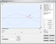
I've got something Freshhhh for you hungry minds out there - the promised visualisation of the direct ascent optimal velocity solver :)
http://www.elwico.pl/~ender-sz/orbiter-pdf/pliki/LaunchMFD-da-velOptimum.zip

From the help dialog:

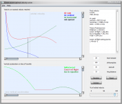
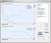
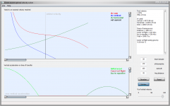
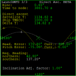
The transfer consists of (currently) 3 phases:
1) Accelerating east to reach a given velocity < orbital velocity
2) Constant velocity flight
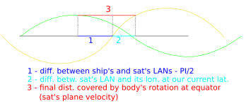
3) Bootleg manouevre to equalise velocity vector with the target

Ad. 1) During the 1st phase, the ship accelerates with the main engines, while using the hovers to counter the gravity. The more velocity you build, the greater the centrifugal force, so the less you have to be accelerating with the hovers.

Ad. 2) In the 2nd phase you also need to be countering the resulting gravity, based on the velocity that you have built up, while covering the required distance.

Ad. 3) In the last phase, the greater your velocity was the use more fuel you will use to equalise the velocity vector. Note, that if there's a big angular difference in orbital planes and your velocity was big, then you will have to lessen the velocity vector initially, which will result in lessening your centrifugal force, finally requiring that you use the hovers more.

The lower window displays vertical acceleration of all three phases as a function of time.
The upper window displays delta v's as a function of the velocity reached in the 1st phase.
I strongly recommend using the velocity slider, which will help you visualise the problem.
The windows are somewhat scalable and the input text edit boxes have important tooltips.

Before doing any calculations, press the Reset button, to get the user values and iterate the velocity for plotting the dv.


In case of any questions, just fire away :)
 

Attachments

  • Too big velocity causes problems in the end.png
    Too big velocity causes problems in the end.png
    47.6 KB · Views: 14
  • Optimal solution.png
    Optimal solution.png
    49.2 KB · Views: 22
  • Great distance  - better accelerate to orbital vel.png
    Great distance - better accelerate to orbital vel.png
    53.5 KB · Views: 14
Last edited:
After quite a busy while, I'm returning to coding Launch MFD. In the long term, my development plan is the following:

  1. Create a smooth, PD controller based, universal autopilot, while trashing the skippy fuzzy logic autopilot
  2. Finally utilize Kwan's Multistage PEG
  3. Maybe work on Direct Ascent sub-program
PID AP is in the final stages of development. I've tested it with success for stock DG and XR series. As far as other popular ships go, the PEG can't adjust itself for them, but you can still use the AP while flying these ships for a atmosphere aided insertion (where you don't pitch up that much, but use the lift to counter gravity instead). The AP will then simply help you minimizing the azimuth error and keeping you wings level. The AP is so smooth, that once you get clear of dense atmosphere, it's possible to continue the ascent with 100x time acceleration. Of course the more FPS, the smoother the controllers behave generally.

I have a request to people who use Launch MFD's fuzzy logic AP to test the attached, PD controller based AP for ships in which the fuzzy AP works (or tries to work). We'll see if it works better or worse. Please give feedback, along with the rockets / ships that you used. Let me stress, that I'm mostly interested in vessels for which insertion with fuzzy autopilot was possible, because we're testing the ability of a controller to reach specified position for various vessels (actually, regardless of the vessel controlled) and nothing more. The ability to define a proper pitch for realistic spacecraft will be subject to 2nd point of the development plan - Multistage PEG.

The latest code is always here: http://sourceforge.net/projects/enjomitchsorbit/

Thanks in advance.
 

Attachments

Last edited:
Enjo,

Glad to hear that development on LaunchMFD is still ongoing. I've been out of it for quite a while (and won't be back developing for orbiter for a while yet unfortunately) but still keep lurking around here now and again.

I know how PID controllers (and thus PID autopilots) work. How did your fuzzy autopilot work?

Also, I took a look at some of the autopilot code. It may be worth taking the tuning parameters into a config file so that (advanced) users can tune the PID controller to their needs rather than relying on hard coded values that may not work with different target vessels.
 
And I'm glad that you returned in one piece from Safari :)

I know how PID controllers (and thus PID autopilots) work. How did your fuzzy autopilot work?
In the definition of a fuzzy autopilot, there's too much error possible, and except maybe for significant linguistic control, like "if some specific value or combination of values, do this", there's little exact (rough) control of values and a limited ability for fine tuning. In Orbiter, the rules of control are simple and I need more value control than rule control. Also, we know that in Orbiter, unlike in reality, you can increase the time acceleration up to 100x (maximal reasonable value for autopilots), and by doing it, you demand the controller to be 100x more accurate, which was too much for the fuzzy autopilot.

Also, I took a look at some of the autopilot code. It may be worth taking the tuning parameters into a config file so that (advanced) users can tune the PID controller to their needs rather than relying on hard coded values that may not work with different target vessels.

I've had such an idea. The plugin would look for a cfg corresponding to the ship's name and try to read values from there, which is the ultimate "leave me alone" solution, and not that hard to implement. But first, while I have time, I'd like to try unifying this as much as it's possible, hence the "Maximal acceleration" thread. I compare the current ship's rotational acceleration with that of a reference ship, for which the values were chosen, and use this ratio as a multiplier of RCS power. This works properly only in space though. In the atmosphere it's all the same, not to mention that making an atmospheric autopilot is very tricky.
 
Weekend bump.

Please read this post and help me testing, as I will be probably releasing the newest version on Monday because between then and October I will have very little time to play with this and I wouldn't like to break anything that works.
 
Something small to help timing the direct ascent launch without the need of using Map MFD.

The great circles were there already, back in the day when I was statically calculating a hypothetical direct ascent, but this time they are done right and in a very clean way.
 

Attachments

  • launch-mfd-great-circles.png
    launch-mfd-great-circles.png
    15.8 KB · Views: 39
Last edited:
Signing off for a while

Hi all,

I'm feeling some sort of a burnout, resulting from quite intense work and a specific kind of neighbors that I have in my current apartment (in Germany it's called "MultiKulti"). I'll be heading off to Poland for some time for relaxation and to hopefully load'em batteries. I won't spend much time in front of computer, surely not developing, or at least that's the plan.

In meantime, I've made a very small thing, which is too small for a release, but it makes me a bit happy, so I wanted to share it :) It's animated Great Circle zooming. See attachment.

Have fun while I'm away.
 

Attachments

Last edited:
Back
Top