- Joined
- Feb 4, 2008
- Messages
- 9,754
- Reaction score
- 1,027
- Points
- 203
Thanks! Looks pretty straightforward, so I shall try it when I get back to my dev machine.splining eh? thats pretty hardcore.
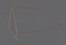
make your spline cage look like this - remember that 'cage' is the operative word.... you want to construct lines in such a way that the surfaces can be drawn between them using "surface modifier".
make sure that the vertexes (green crosses) are welded up... so in this pic, you have 6 lines and 4 vertexes, then add the modifier.... i'm not sure that surface will draw a surface over a shape defined with more than 4 vertexes due to technical limitations, it being very old basically.
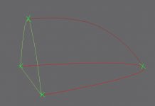
Does this look correct? I have tried using the Surface modifier but it doesn't work correctly, most likely due to those limitations you're referring to.make sure that the vertexes (green crosses) are welded up... so in this pic, you have 6 lines and 4 vertexes, then add the modifier.... i'm not sure that surface will draw a surface over a shape defined with more than 4 vertexes due to technical limitations, it being very old basically.
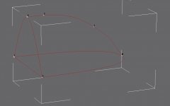
OK, thanks. I guess the "4 per surface" got me.lol. yeah thats because you have about a thousand vertexes... remember i said no more than 4 per surface... rather than have lots of verts and lots of lines, you should use as few as possible and edit the curves, using bezier corners to make the shapes you want.

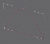
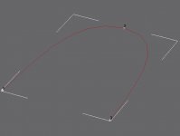
Well, the problem with the upper arc is that it begins with a straight section before it curves down. I have attached images of the various shapes.well for a start you still have 2 more verts than you need on that upper arc, which will make surface fail.
as for your problem, i can't tell if you actually have 2 verts at those intersections, basically you should have 3 separate elements... the back shape, made of 3 lines and 3 verts, with a vertex on the apex of the curve.. same again for the lower shape but minus the straight edge so you have 2 lines and 3 verts (ends and mid-arc). then you should just have 1 line with 2 verts as an arc connecting those apexes...if you put those shapes together they should weld up just fine. otherwise perhaps try fusing them if you can with the 'fuse' button if you have one.
Well, the problem with the upper arc is that it begins with a straight section before it curves down. I have attached images of the various shapes.
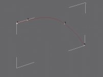
Maybe you can take a look at it? I could send you the .gmax file for you to examine. Everything lines perfectly, no misaligned lines or verts.then you'll need to add more lines and verts as needed to make the shape.
i can't see why thats failing to weld though, splines are a pain... all the parts are attached together as one shape before you try and weld no?
otherwise break/detach the arcs into separate lines perhaps?
Well, the problem is step 3, the welding.It just refuses to weld any of the vertices.4 verts per surface other than that, sounds ok, is it working now? one thing you may wanna try is to delete the arcs on one side, then try welding it up, you can mirror the resulting mesh later. "fuse" helps. if you have that option..
How do you break the splines into separate lines? I haven't found anything that does this, but then I just be overlooking it.none? you've tried increasing the threshold by massive amounts? i've had problems like this, but i've generally solved it by breaking the splines apart into separate lines, or splitting the shape in half.
Yes, didn't turn out so well. I'll post a screenie once get back to my dev machine in about 30 minutes.select segment, then 'detach' button. have you just tried applying the surface modifier to the unwelded shape though?