-
ORBITER-FORUM will be temporarily closed at 2026-07-23 18:00 UTC while we complete some OF maintenance tasks. The amount of downtime is expected to take up to one hour, but probably less.
You are using an out of date browser. It may not display this or other websites correctly.
You should upgrade or use an alternative browser.
You should upgrade or use an alternative browser.
News Gallery of add-ons in development
- Thread starter Matias Saibene
- Start date

- Joined
- Feb 6, 2008
- Messages
- 38,938
- Reaction score
- 3,937
- Points
- 203
- Location
- Wolfsburg
- Preferred Pronouns
- Sire
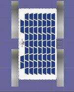
It is important to set up the axles in a way that can work in Blender, because it gives us the data we need (position, vectors) to animate the thing in Orbiter.
How do you do that, is it a Null object in Blender? Is it possible to export the axes in a text file? (or even a C++ header file?!)
How do you do that, is it a Null object in Blender? Is it possible to export the axes in a text file? (or even a C++ header file?!)
1. I set the Cursor to 'World Origin' which is xyz(0,0,0) obviously.
2. I apply the Mirror modifier to my axles, then select them all and 'Set Origin to 3D Cursor'. Now their vertices coordinates are calculated from there.
3. In 'Edit Mode', I select all the vertices of 1 of these axles, which gives me the 'Median', which tells us where the object is in regard of the World Origin. Remember you have to swap Y & Z when using the data in Visual Studio.

4. To get the vector that defines the orientation of the axle, select each of the two discs that cap the axle and note their coordinates :


5. Then from these two sets of coordinates (median point of each of the discs), figure out a vector
x1 = -3.06143
y1 = -0.904082
z1 = 1.04309
x2 = -3.06067
y2 = -1.0036
z2 = 0.943966
I'm not good-at-maths, so the other day I asked the AI (Gemini 2.5, in this case) who nailed it. Like :


It might seem a lenghty process but of course, the 4 axles are symmetrical (relatively to our World Origin or _V(0,0,0). So getting the other points/vectors is easy.
diogom
Well-known member
- Joined
- Aug 2, 2010
- Messages
- 1,564
- Reaction score
- 927
- Points
- 128
- Website
- github.com
- Preferred Pronouns
- he/him
Are steps 1 and 2 redundant? As long as the median is set to global the reference of the vertices should be the world origin, independent of the object's own origin. Always matched up for me anyway, on 2.83.5.
You can add an 'empty', Plain Axes in Blender, then with that object selected, in the 'Object' tab under 'Orbiter Object Panel' select 'Include Position'.
Tell Blender to 'Build Include File', (Output tab, Orbiter Output Panel) it will give you a constexpr VECTOR3:
constexpr VECTOR3 MyAxes_loc = {0.0000, 0.7722, 14.6386};
That will be transformed as needed as part of the export.
If that helps.
Tell Blender to 'Build Include File', (Output tab, Orbiter Output Panel) it will give you a constexpr VECTOR3:
constexpr VECTOR3 MyAxes_loc = {0.0000, 0.7722, 14.6386};
That will be transformed as needed as part of the export.
If that helps.
- Joined
- Feb 6, 2008
- Messages
- 38,938
- Reaction score
- 3,937
- Points
- 203
- Location
- Wolfsburg
- Preferred Pronouns
- Sire
")


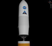
I followed the specifications of this document, and beautifully the engines fit perfectly. To the centimeter. This configuration allow 6° of gimbal, and the good thing is that I have working code for that. I figured it out for the Proton, which has a similar engine layout. And the Proton is no joke, but this Ares V is a real mammoth, in size and technology.
NASA - Ares V & RS-68


NASA - Ares V & RS-68


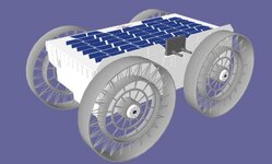
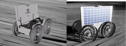
Another rover.
 www.astrolab.space
I can make this drivable. I need to fill the inside.
FLIP Rover – Astrolab
www.astrolab.space
I can make this drivable. I need to fill the inside.
Attachments
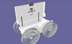


In orbiter2016. I can try 2024.
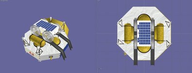
I need to build the carrier. It is part of the Griffin1.
Astrobotic's Griffin-1 lunar lander
Astrobotic's Griffin Mission One (Griffin-1) is a lunar lander mission that will land at the Nobile Crater at the lunar South Pole.
I need to build the carrier. It is part of the Griffin1.
Astrobotic's Griffin-1 lunar lander
Astrobotic's Griffin Mission One (Griffin-1) is a lunar lander mission that will land at the Nobile Crater at the lunar South Pole.
Attachments


Really not too bad for a first import. Looks like everything is there (for the 1st stage, I mean).
Unsurprisingly, the launchpad will have to be refurbished a bit. The first stage alone is almost towering the lightning rod lol...

Unsurprisingly, the launchpad will have to be refurbished a bit. The first stage alone is almost towering the lightning rod lol...
Last edited:
Similar threads
- Replies
- 12
- Views
- 4K
- Replies
- 143
- Views
- 25K
- Replies
- 34
- Views
- 9K
- Replies
- 10
- Views
- 5K
- Replies
- 156
- Views
- 44K