Science Crowdfunding campaign announced: Nanotech: from air to space

...
Your conclusions are based on three equations on your favorite source:
f_geo is more or less voodoo there, the author provides some approximations without experimental confirmation.
if you paid as much attention to math as I did, you would notice the following relation:
This term really increases slowly with decreasing wire radius r:
[math]Y = d \cdot \ln \left( \frac{f_{geo}}{r} \right)[/math]
But the effect of the term is inverse proportional on the thrust force, the larger term Y, the lower the thrust force:
[math]F=\frac{2 \pi e_0 L V(V-V0)}{Y}[/math]
As predicted by other less esoteric sources and peer reviewed papers: The smaller the wire diameter, the lower the thrust.

That page actually doesn't show that when you want to maximize thrust there is a dependence on the radius in the numerator also in the formula for the thrust. I should have linked this page:

Lifter theory.
Force/Power optimization
by Evgenij Barsoukov
Courtesy of Evgenij Barsoukov
Created on April 30, 2002 - JLN Labs - Updated on April 30, 2002
...
3. Corona wire radius optimization
Radius was changed from gauge 50 (0.015 mm) to gauge 20 (1.5mm). Resulting thrust/power relation is given below :

fpim10.gif


It is great to see, that efficiency does not change, but thrust does! See below absolute thrust/radius dependence :

fpim11.gif


With decreasing radius thrust increases a lot, without losing efficiency!

Conclusion

Increasing the wire/collector distance by simultaneous increase of wire/collector lenght can allow to achieve thrust/power ratios up to 40g/W.
Decreasing wire radius increases thrust without degrading thrust/power ratio.http://jnaudin.free.fr/html/liftfpwr.htm

I'll change that link in the crowdfunding web page.

BTW, that wikipedia page on the Ionocraft was giving the diameters in American Wire Gauge(AWG) units, which, annoyingly, doesn't increase with increasing gauge size and isn't even linear:

Corona wire
The corona wire is usually, but not necessarily, connected to the positive terminal of the high voltage power supply. In general, it is made from a small gauge bare conductive wire. While copper wire can be used, it does not work quite as well as stainless steel. Similarly, thinner wire such as 50 gauge tends to work well compared to more common, larger sizes such as 30 gauge, as the stronger electric field around the smaller diameter wire results in better ionisation and a larger corona. current.https://en.wikipedia.org/wiki/Ionocraft#Corona_wire

The 50 gauge wire in AWG units is actually only 1/10th the diameter of the 30 gauge wire.


Bob Clark
 
Last edited:
That is a purely mathematical simulation with the following warning:

Note that spark discharge might occur before 100kV.

By the lack of any other information, I have to assume he used the constants stated on top, so he is assuming that he can always put 40 kV through 200 mm of wire there, regardless how thin the wire gets. He does not say the material of the wire or even the assumed current for the thrust, which is conveniently hidden.

As the resistance of a wire of a given length increases by decreasing radius, you have to assume that keeping voltage constant requires less current. But he does not say if he did so, his assumed formula is stated, but not plot for checking the data.

And then, remember the old reality of a fuse. A thin wire with too much current melts. Even Nanotubes do so. Nanotubes are estimated to decompose in contact with air at a temperature of 750°C already (not 2600°C as in vacuum).

It is not experimentally. It is just a stupid mathematical simulation of punching numbers into something that looks like Mathematica and let it plot the results by the formulas. Anything not stated in the equation is ignored - as shown above.

And it was not done by you. And not peer reviewed, it is still just fan boy work. And what can you actually do there? What is your competence?

PS: The formula on Wikipedia is using basic physical dimensions and not AWG or SI system.
 
..so he is assuming that he can always put 40 kV through 200 mm of wire there, regardless how thin the wire gets. He does not say the material of the wire or even the assumed current for the thrust, which is conveniently hidden.
Ja.. you can put a 'zillion' volts on any 'wire'.. it's just the current (or discharge) that will turn it into fuse-wire ;)
 
Ja.. you can put a 'zillion' volts on any 'wire'.. it's just the current (or discharge) that will turn it into fuse-wire ;)

Yeah, a static discharge can easily reach 100 kV, but it won't kill you. :lol:
 
That is a purely mathematical simulation with the following warning:
Note that spark discharge might occur before 100kV.
By the lack of any other information, I have to assume he used the constants stated on top, so he is assuming that he can always put 40 kV through 200 mm of wire there, regardless how thin the wire gets. He does not say the material of the wire or even the assumed current for the thrust, which is conveniently hidden.
As the resistance of a wire of a given length increases by decreasing radius, you have to assume that keeping voltage constant requires less current. But he does not say if he did so, his assumed formula is stated, but not plot for checking the data.
And then, remember the old reality of a fuse. A thin wire with too much current melts. Even Nanotubes do so. Nanotubes are estimated to decompose in contact with air at a temperature of 750°C already (not 2600°C as in vacuum).
It is not experimentally. It is just a stupid mathematical simulation of punching numbers into something that looks like Mathematica and let it plot the results by the formulas. Anything not stated in the equation is ignored - as shown above.
And it was not done by you. And not peer reviewed, it is still just fan boy work. And what can you actually do there? What is your competence?
PS: The formula on Wikipedia is using basic physical dimensions and not AWG or SI system.

Carbon nanotubes by theoretical evidence may be able to carry up to 10^9 amps per square cm, 1,000 times as much current as copper:

https://en.wikipedia.org/wiki/Carbon_nanotube#Electrical_properties

This would put copper at about 1,000,000 amps per square cm. Then the amount of current that could be carried in the microscale wires discussed in these lifter experiment pages would be in the range of 10's of amps while the current mentioned there that was actually carried was only in the range of microamps. And the nanotubes current capacity limits would be even further above the current they had to carry.

There is the separate issue of electrical breakdown of air. When this happens there is a loss of thrust. This is dependent on the voltage over the distance between the electrodes, not the current over the wires. It is several thousand volts per cm but the voltages used by the lifters are in this range. So you are right it would need to be tested to see if using nanotubes to get the needed thrust to lift both the craft and power supply the voltage would so high to cause breakdown of air.

About the formula for the thrust, other research teams have derived similar formulas, including ones published in peer-reviewed research journals. See for example eq. 41 here:

An analysis of the Brown–Biefeld effect.
Reuven Ianconescu, Daniela Sohar, Moshe Mudrik
Journal of Electrostatics
Volume 69, Issue 6, December 2011, Pages 512–521
http://arxiv.org/pdf/1011.1393v3.pdf

They all show the thrust increases with decreasing wire radius.

Note that using nanotubes for the wires would be trebly more efficient. First, their extremely small diameters should significantly increase the thrust. Second, their small weight compared to metal wires should greatly reduce the weight. And third, their increased conductivity, i.e., reduced resistance, means less power would be required to achieved the same results which means a smaller, lighter power supply, further reducing the weight of the craft.

Putting these factors together means there's a very good chance we can finally get an independently flying lifter able to carry its own power supply. Note this would also work to get a real hoverboard (Back to the Future would only have been off by 1 year) and personal jetpacks. Note also it makes the U.S. Army's billion dollar V-22 Osprey obsolete before being fully deployed.


Bob Clark
 
Last edited:
About the formula for the thrust, other research teams have derived similar formulas, including ones published in peer-reviewed research journals. See for example eq. 41 here:

An analysis of the Brown–Biefeld effect.
Reuven Ianconescu, Daniela Sohar, Moshe Mudrik
Journal of Electrostatics
Volume 69, Issue 6, December 2011, Pages 512–521
http://arxiv.org/pdf/1011.1393v3.pdf

They all show the thrust increases with decreasing wire radius.

Are you kidding me?

The paper only shows again, that lifting force increases with current. No conclusion with decreasing wire radius increasing Lift force and no calculation claiming so - the increase in Ei by smaller wire radius is smaller than other factors. The only advantage mentioned is that smaller wires produce a simpler electric field for the calculations.


Don't try to cheat me that easily - if you cite it, I might read it.

The resistivity of SWNTs is measured on the order of 10E-4 Ohm/cm, which is only ten times better than a 1mm copper wire.
 
Are you kidding me?
The paper only shows again, that lifting force increases with current. No conclusion with decreasing wire radius increasing Lift force and no calculation claiming so - the increase in Ei by smaller wire radius is smaller than other factors. The only advantage mentioned is that smaller wires produce a simpler electric field for the calculations.
Don't try to cheat me that easily - if you cite it, I might read it.
The resistivity of SWNTs is measured on the order of 10E-4 Ohm/cm, which is only ten times better than a 1mm copper wire.

I'm referring to the term subtracted off at the end of the formula. It gets smaller as the radius gets smaller. There is the effect of the radius in the denominator, but because it is in a log its effect is less than the linear term subtracted off at the end, as can be confirmed by plugging in numbers. And all reports state the thrust increases with decreasing wire radius.

There are two different aspects of nanotubes as conductors, its current carrying ability, according to theory 1,000 times better, and its resistivity about 10 times better.


Bob Clark
 
Even if nanotubes had such a current rating.. there would always be a stumbling block with what it connects to.
If you going to drive it with such high voltage and currents there's a good possibility of burning up the contact points.
It could work but it would be very risky. Construction methods will determine this and it might be very costly in the end.
;)
 
I'm referring to the term subtracted off at the end of the formula. It gets smaller as the radius gets smaller. There is the effect of the radius in the denominator, but because it is in a log its effect is less than the linear term subtracted off at the end, as can be confirmed by plugging in numbers. And all reports state the thrust increases with decreasing wire radius.

Sorry - what are you talking about? Which equation number?

In your cited paper, you can find the following equation for the thrust force (41):

[math]F = 4.792{\pi}{\epsilon_{0}}{l}\frac{V_0}{b}\left ( \frac{V_0}{1.011 \ln{ \left ( b / a \right )} + 1.3035} - 3 \times 10^6 \left (a + 0.03\sqrt{a} \right ) \right )[/math]


a is anode wire radius
b is air gap
[math]V_0 [/math] is Voltage.
l is perimeter, or length of the anode wire.

Which term does show a positive effect of decreasing wire radius a on lift force F?
 
Last edited:
Ye olde cranium is kicking into gear :lol:

OK! say you get the thing working...
Now power supply weight becomes a problem, and are the forces produced by the device capable of overcoming this.

At the moment one can make a relatively light weight, high voltage power supply as long as you keep your current rating down.
As soon as you ramp up the current weight becomes a big problem.. and the stuff gets really heavy.

Maybe large 3D printers might overcome this with Carbon printing, but carbon is brittle and screams at you thermally and sonically when pushed to it's limit.
One can reduce the size by driving up the frequency, but then insulation becomes a big problem, especially at high Vs and Is = more weight.
Insulation for any high voltage and currents is also a baaaitch.. and heavy too. One little indentation and you can have a massive explosion... just like that.

There will be a limit to size reduction/required rating tradeoff, as you'll need higher frequency to obtain smaller size (light weight) and higher power, but will be limited to the high voltage/current ratings insulation dimensions...
So all in all you're probably fooked on this one :)

I'll keep my money ;)
 
Last edited:
Sorry - what are you talking about? Which equation number?

In your cited paper, you can find the following equation for the thrust force (41):

[math]F = 4.792{\pi}{\epsilon_{0}}{l}\frac{V_0}{b}\left ( \frac{V_0}{1.011 \ln{ \left ( b / a \right )} + 1.3035} - 3 \times 10^6 \left (a + 0.03\sqrt{a} \right ) \right )[/math]


a is anode wire radius
b is air gap
[math]V_0 [/math] is Voltage.
l is perimeter, or length of the anode wire.

Which term does show a positive effect of decreasing wire radius a on lift force F?

Yes. That is the equation. When the radius a gets large you'll be subtracting off a large number within that outer parentheses.

However, that equation is a complicated expression. Sometimes it also gets smaller with decreasing values of a. It depends on the sizes of the distance b and voltage V0. And it even has a point where it blows up to infinity, where the denominator is 0.

I was puzzled by that blow up point. But I think it's reflecting the fact that there is a corona around the wire and if the distance b gets too small then the collector is in the corona and it acts just like as if there is breakdown in the air.

You might like to see how the graph looks and changes with different values of b and V0, graphed in terms of the radius a.

In any case I can give a heuristic argument for why very small diameter wires might be effective. You need high ionization of the air to get high thrust, though below the breakdown voltage.

Sharp points are known to produce a corona discharge:

Corona discharge.
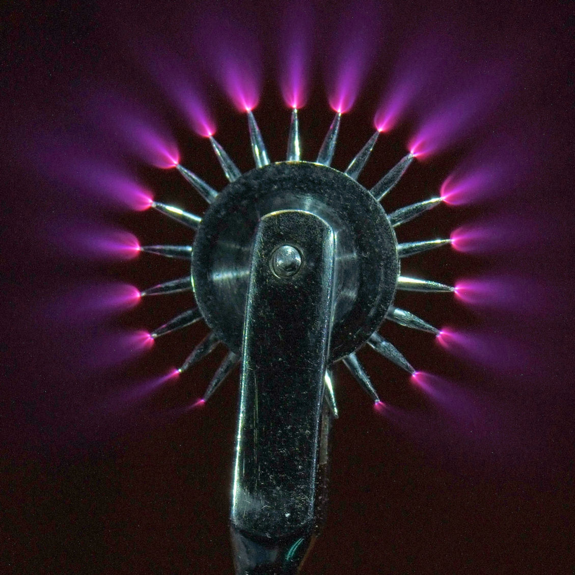
When the potential gradient (electric field) is large enough at a point in the fluid, the fluid at that point ionizes and it becomes conductive. If a charged object has a sharp point, the electric field strength around that point will be much higher than elsewhere. Air near the electrode can become ionized (partially conductive), while regions more distant do not. When the air near the point becomes conductive, it has the effect of increasing the apparent size of the conductor. Since the new conductive region is less sharp, the ionization may not extend past this local region. Outside this region of ionization and conductivity, the charged particles slowly find their way to an oppositely charged object and are neutralized.
Plasma_wheel_2_med_DSIR2018.jpg

https://en.wikipedia.org/wiki/Corona_discharge

Then for very small diameter wires you might need much smaller voltage to get the air ionization effect. In fact, it might only be in the hundreds of volts instead of thousands. You could then also have a shorter gap between the emitter and collector, resulting in a smaller craft. And not needing such high voltage would result in a smaller, simpler, lighter power supply.

Some researchers in experiments with electrohydrodynamic devices have also taken to using sharp pins as the emitter instead of a long wire. See the last papers discussed here:

Carbon nanotubes for "ionic wind" craft or "ionocraft".
http://exoscientist.blogspot.com/2016/02/carbon-nanotubes-for-ionic-wind-craft.html


Bob Clark
 
Back
Top