You are using an out of date browser. It may not display this or other websites correctly.
You should upgrade or use an alternative browser.
You should upgrade or use an alternative browser.
General Question ADI ball layout
- Thread starter martins
- Start date
Another update: this time the alternative ball layout with poles at yaw +/-90 and 360 deg pitch range, i.e. the same layout as the Shuttle ADI (links in the first post). This required another nasty texture design, which I am including in case it's of use to anyone. BTW, do any of the Shuttle addons implement this instrument (in a pre-glass cockpit setup)? I would be quite interested to compare.
This mode isn't very useful without a way to define a yaw reference, so I guess I'll do that next.
This mode isn't very useful without a way to define a yaw reference, so I guess I'll do that next.
Attachments
- Joined
- Feb 6, 2008
- Messages
- 38,965
- Reaction score
- 3,937
- Points
- 203
- Location
- Wolfsburg
- Preferred Pronouns
- Sire
BTW, do any of the Shuttle addons implement this instrument (in a pre-glass cockpit setup)?
Not that I know - I would really like to have the original cockpit layout in SSU, but there is still enough work left for the glass cockpit, before we can even think about this one. But since we do VCs, I suspect such a ADI ball implementation would end up being drawn as sphere.
Apollo (and Gemini IIRC) cockpits used this same ADI format, ie, 360° pitch, +/- 90° yaw.

FWIW, Attitude MFD uses it also, but in text, not in graphics of course.
FWIW, Attitude MFD uses it also, but in text, not in graphics of course.
- Joined
- Feb 7, 2008
- Messages
- 299
- Reaction score
- 0
- Points
- 16
- Location
- nassp.sf.net
- Website
- nassp.sf.net
Apollo [...] cockpits used this same ADI format...
Correct, and in Project Apollo - NASSP we have an fully functional FDAI (the device is called FDAI = Flight Director Attitude Indicator in Apollo actually). As you already noticed, it's pretty much different to an "artificial horizon", especially the references and the Euler angles used are different (matching the IMU): http://nassp.sf.net/wiki/CSM_FDAI
Cheers
Tschachim
Attachments
Last edited:
Yes, essentially it's a projection of the vessel orientation onto a different reference plane. For the "standard" layout the Euler angles are referenced against the pitch=0 plane, while for the "alternative" layout they are referenced against the yaw=0 plane. Transforming pitch and yaw was quite straightforward, while transforming the bank angle had me scratch my head for a bit ... :lol:.As you already noticed, it's pretty much different to an "artificial horizon", especially the references and the Euler angles used are different (matching the IMU)
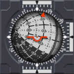
One potentially confusing feature of the "alternative" layout is that it doesn't correspond to the "artificial horizon" reference of the surface HUD anymore. This is particularly apparent for the bank indicator. Look at the attached image. The HUD indicates a bank angle of about 30 degrees, while the ADI indicator says 0. This is because the vessel is aligned with the local pitch=constant plane. (in other words, the yaw=90 pole is in the vessel's local y=0 plane).
Therefore, the ADI bank indicator is consistent with the ball's frame of reference, but possibly not very intuitive to interpret. I wonder if it would be better to always reference the bank indicator against the pitch=90 pole, regardless of the chosen ADI layout.
Attachments
I find the ADI roll indicator very intuitive for flying in space, but perhaps that is because I am used to it with Attitude MFD and NASSP. The rotational attitude thrusters align nicely with the axes of the ball so that you can readily see on the ball what direction a manoeuvre is going to take you. The ADI ball is meant to show different things in space - pitch, yaw and roll - compared to what you are normally interested in for surface operations - pitch, heading and bank. I wouldn't normally use the surface HUD in space anyway and restrict its use to atmospheric/surface operations in conjunction with Surface MFD (they are called Surface for a reasonTherefore, the ADI bank indicator is consistent with the ball's frame of reference, but possibly not very intuitive to interpret. I wonder if it would be better to always reference the bank indicator against the pitch=90 pole, regardless of the chosen ADI layout.
") ). I think you should choose a reference system and stick to it for all three axes - mixing reference systems will be even more counter-intuitive IMHO. This is probably why attitude indicators for aircraft don't contain a heading indicator (it is on the HSI IIRC) to minimise potential confusion. Perhaps one of the pilots on the forum would care to comment? EDIT: To clarify, I have no issues at all with the ADI ball showing pitch, heading and bank for surface operations as long as it is selectable between that and pitch, yaw and roll mode. But to use pitch and yaw references from one frame and a bank reference from another frame... :nono:
). I think you should choose a reference system and stick to it for all three axes - mixing reference systems will be even more counter-intuitive IMHO. This is probably why attitude indicators for aircraft don't contain a heading indicator (it is on the HSI IIRC) to minimise potential confusion. Perhaps one of the pilots on the forum would care to comment? EDIT: To clarify, I have no issues at all with the ADI ball showing pitch, heading and bank for surface operations as long as it is selectable between that and pitch, yaw and roll mode. But to use pitch and yaw references from one frame and a bank reference from another frame... :nono:How do you define your reference frame for your ADI ball? One thing that has always bugged me a little is that the Orbit HUD has its pitch=0 reference as the orbital plane. Real life space programs that I have seen use a frame that is typically defined such that the +z-axis is aligned with the velocity vector and the +x-axis is aligned with the orbital angular momentum vector (those vectors in Orbiter's left hand frame). This system simplifies to the common LVLH frame seen in manned spaceflight programs for circular orbits (they normally fly in very near circular orbits anyway).
Thanks for that reply. The fact that up to now I only had a decidedly hazy notion of the difference between bank and roll, and between heading and yaw shows just how much I really know about aerospace engineering :lol:. Anyway, I am learning fast ... So far I haven't really thought much about the reference frame of the ADI ball, and I am using a kind of "dummy" frame at the moment, given by the local vertical (of the LVLH frame), and the cross product of the local vertical and planet axis (i.e. a heading-oriented system). I agree that your suggestion of using the orbital velocity vector and the angular momentum vector is useful. I am planning to make the reference frame user-selectable. For example, during docking, it might be useful to have a frame that is aligned with the "dir" and "rot" vectors of the chosen docking port.I find the ADI roll indicator very intuitive for flying in space, but perhaps that is because I am used to it with Attitude MFD and NASSP. The rotational attitude thrusters align nicely with the axes of the ball so that you can readily see on the ball what direction a manoeuvre is going to take you. The ADI ball is meant to show different things in space - pitch, yaw and roll - compared to what you are normally interested in for surface operations - pitch, heading and bank. I wouldn't normally use the surface HUD in space anyway and restrict its use to atmospheric/surface operations in conjunction with Surface MFD (they are called Surface for a reason
How do you define your reference frame for your ADI ball? One thing that has always bugged me a little is that the Orbit HUD has its pitch=0 reference as the orbital plane. Real life space programs that I have seen use a frame that is typically defined such that the +z-axis is aligned with the velocity vector and the +x-axis is aligned with the orbital angular momentum vector (those vectors in Orbiter's left hand frame). This system simplifies to the common LVLH frame seen in manned spaceflight programs for circular orbits (they normally fly in very near circular orbits anyway).
And yes, the bank (or rather, roll) indicator will remain consistent with the reference frame. The suggestion in my previous post wasn't, erm, well thought through. :facepalm:
^ My first ever use of the facepalm smilie! Good thing I am using it on myself.
- Joined
- Feb 7, 2008
- Messages
- 299
- Reaction score
- 0
- Points
- 16
- Location
- nassp.sf.net
- Website
- nassp.sf.net
I am planning to make the reference frame user-selectable. For example, during docking, it might be useful to have a frame that is aligned with the "dir" and "rot" vectors of the chosen docking port.
Changing the reference depending on your situation is how it's done in reality, too. The reference is normally called "REFSMMAT" for "Reference to Stable Member Matrix" ([ame="http://en.wikipedia.org/wiki/Refsmmat"]Refsmmat - Wikipedia, the free encyclopedia[/ame]) since the FDAI RPY angles are (more or less) identical to the IMU stable member RPY angles. In Apollo you begin with the "Pad REFSMMAT", which is the LVLH frame on pad at liftoff. In a typical Moon landing mission you change it for the TLI burn the first time (to LVLH or "LV/burn vector" at ignition point/time of the TLI burn, I'm not sure right now).
My first ever use of the facepalm smilie! Good thing I am using it on myself.
:lol: I'm using it on myself all the time, this one is even better: :beathead:
Cheers
Tschachim
Last edited:
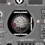
Some more progress: I've implemented an AttitudeReference class to which the ADI ball is now connected. Currently there are three reference frames to choose from:
All configurations for the ball and attitude reference are done via Lua commands. I still want to do more reference frames, for example an inertial reference where you can either choose the orientation in some way, or simply by saying "keep orientation fixed in current position". Also I want to implement the deviation cross-hairs of the original ADI. They could come handy to represent the direction of a target, or the lateral displacement of a docking port (the "+" symbol of the Docking HUD).
I am starting to get quite fond of this little gadget. A lot of information in a compact instrument. Would be a shame to have it limited to the Shuttle-A. I hope that the implementation is modular enough to allow it to be ported to other vessels easily.
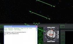
- local vertical / cross product of local vertical and planet axis (equivalent to Surface HUD mode) [image 1]
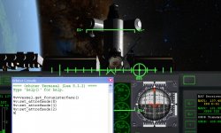
- orbit momentum vector / orbital velocity vector (equivalent to Orbit HUD rotated by 90 degrees [image 2]
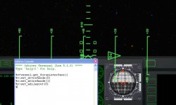
- Aligned with docking port orientation from the IDS signal of a given NAV receiver (equivalent to the "X" symbol of the Docking MFD) [image 3]
All configurations for the ball and attitude reference are done via Lua commands. I still want to do more reference frames, for example an inertial reference where you can either choose the orientation in some way, or simply by saying "keep orientation fixed in current position". Also I want to implement the deviation cross-hairs of the original ADI. They could come handy to represent the direction of a target, or the lateral displacement of a docking port (the "+" symbol of the Docking HUD).
I am starting to get quite fond of this little gadget. A lot of information in a compact instrument. Would be a shame to have it limited to the Shuttle-A. I hope that the implementation is modular enough to allow it to be ported to other vessels easily.
Attachments

Extra reference attitudes I can think of:
* commanded attitude (just about anything, set via Lua and C API, very nice for AP-assisted hands-on control)
* (if the above is not flexible enough,") RVel vector and its negation - for speed nulling)
RVel vector and its negation - for speed nulling)
* stars and Solar system bodies, unidentified flying objects
* commanded attitude (just about anything, set via Lua and C API, very nice for AP-assisted hands-on control)
* (if the above is not flexible enough,
RVel vector and its negation - for speed nulling)* stars and Solar system bodies, unidentified flying objects
- Joined
- Feb 7, 2008
- Messages
- 299
- Reaction score
- 0
- Points
- 16
- Location
- nassp.sf.net
- Website
- nassp.sf.net
Also I want to implement the deviation cross-hairs of the original ADI.
They are called "error needles" by the way.
I am starting to get quite fond of this little gadget. A lot of information in a compact instrument.
Yes, indeed!
May I suggest you keep your current reference frames, add an ecliptic reference frame, and allow the user to define an offset from any of these instead? This way, the ball's reference frame (this is the REFSMMAT that Tschachim mentioned earlier) is defined as a selectable base frame plus an rotation offset from that.I still want to do more reference frames, for example an inertial reference where you can either choose the orientation in some way, or simply by saying "keep orientation fixed in current position".
It would be nice if the user could define a target attitude with respect to the current REFSMMAT, and that it could be defined both numerically (ie, target PYR values) or by selection (ie, select ship, docking port, body, etc).Also I want to implement the deviation cross-hairs of the original ADI. They could come handy to represent the direction of a target, or the lateral displacement of a docking port (the "+" symbol of the Docking HUD).
Would be nicer still if we could draw it in an MFDWould be a shame to have it limited to the Shuttle-A. I hope that the implementation is modular enough to allow it to be ported to other vessels easily.
Last edited:
This is essentially what I had in mind. Possibly even not just a static offset, but one that linearly depends on time.May I suggest you keep your current reference frames, add an ecliptic reference frame, and allow the user to define an offset from any of these instead? This way, the ball's reference frame (this is the REFSMMAT that Tschachim mentioned earlier) is defined as a selectable base frame plus an rotation offset from that.
S'pose so, but it was a nice break from the usual virtual stuff to get my hands dirty designing an actual piece of hardware for a change ...Would be nicer still if we could draw it in an MFD
I have just uploaded a new beta (101016) that contains my implementation of the ADI for the Shuttle-A 2D panel (altough the rest of the panel redesign isn't quite finished yet).
If you want to give it a try, you should run the introduction and demo in Tutorials\ADI training (and be prepared for the test at the end).
Let me know if you find any ADI-related bugs or missing features.
If you want to give it a try, you should run the introduction and demo in Tutorials\ADI training (and be prepared for the test at the end).
Let me know if you find any ADI-related bugs or missing features.
Similar threads
- Replies
- 6
- Views
- 4K
- Replies
- 16
- Views
- 4K
- Replies
- 1
- Views
- 4K