Discussion Trying to render a functional VC (starting small)

N_Molson

Addon Developer
Addon Developer
Donator
Joined
Mar 5, 2010
Messages
10,002
Reaction score
4,418
Points
203
Location
Toulouse
My objective here is to create a basic but functional VC for the ShuttlePB, and learn how to do it in the process.

I have my cockpit set up with two 'squares' (each made of 4 vertices and 2 triangles), on which I want, as a first exercise, to display the two 'default' Orbiter MFDs.

1763416015080.png

These two 'wannabe MFDs' are also known as 'MeshGroup 7' for the Right one & 'MeshGroup 8' for the Left one. This is a lightly modded Shuttle PB, there's only 1 mesh, index 0.

1763416170809.png

I managed to 'enable' the Virtual Cockpit using 'clbkLoadVC'. But that's the best I could do studying the samples & the documentation.

bool ShuttlePB::clbkLoadVC (int id)
{
static VCMFDSPEC mfds_left = { 0, 7 };
static VCMFDSPEC mfds_right = { 0, 8 };

// Left & Right MFDs
oapiVCRegisterMFD(MFD_LEFT, &mfds_left);
oapiVCRegisterMFD(MFD_RIGHT, &mfds_right);

// Pilot's eyes location
SetCameraOffset(_V(0, 0.8, 0));

return true;
}

My question is : what am I missing here ? Answer : the meshgroup UV coordinates.

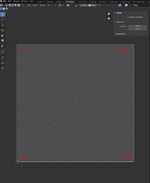
Note : functional Blender material setting for the MFDs :
1763425660364.png
 

Attachments

Last edited:
The corners of the MFD mesh should map the surface where the MFD will be painted: UV coords (0,0), (0,1), (1, 0) and (1,1).
 
I have this :
 

Attachments

  • UVcoordsVC.png
    UVcoordsVC.png
    41.1 KB · Views: 8
Add those coordinates to your mesh. At the end.
Code:
MATERIAL 12
TEXTURE 0
LABEL rghtmfd
GEOM 6 2
0.25326 0.48826 -0.37594 0 0 -1 -0 -1
0.07326 0.48826 -0.37594 0 0 -1 -1 -1
0.25326 0.30826 -0.37594 0 0 -1 -0 -0
0.25326 0.30826 -0.37594 -0 -0 -1 -0 -0
0.07326 0.48826 -0.37594 -0 -0 -1 -1 -1
0.07326 0.30826 -0.37594 -0 -0 -1 -1 -0
0 2 1
3 5 4
you'll only have 4 but you get the idea.
 
Tried this but no luck so far :
LABEL Group_7
MATERIAL 3
TEXTURE 0
FLAG 0
GEOM 4 2
0.2555 -0.2094 1.3796 0.0000 0.0000 -1.0000
0.4560 -0.2094 1.3796 0.0000 1.0000 -1.0000
0.2555 -0.0090 1.3796 1.0000 0.0000 -1.0000
0.4560 -0.0090 1.3796 1.0000 1.0000 -1.0000
3 1 2
2 1 0
LABEL Group_8
MATERIAL 3
TEXTURE 0
FLAG 0
GEOM 4 2
-0.2555 -0.2094 1.3796 0.0000 0.0000 -1.0000
-0.4560 -0.2094 1.3796 0.0000 1.0000 -1.0000
-0.2555 -0.0090 1.3796 1.0000 0.0000 -1.0000
-0.4560 -0.0090 1.3796 1.0000 1.0000 -1.0000
3 2 1
2 0 1

and this, still no luck :

LABEL Group_7
MATERIAL 3
TEXTURE 0
FLAG 0
GEOM 4 2
0.2555 -0.2094 1.3796 0.0000 0.0000 -1.0000 0 0
0.4560 -0.2094 1.3796 0.0000 0.0000 -1.0000 0 1
0.2555 -0.0090 1.3796 0.0000 0.0000 -1.0000 1 0
0.4560 -0.0090 1.3796 0.0000 0.0000 -1.0000 1 1
3 1 2
2 1 0
LABEL Group_8
MATERIAL 3
TEXTURE 0
FLAG 0
GEOM 4 2
-0.2555 -0.2094 1.3796 0.0000 0.0000 -1.0000 0 0
-0.4560 -0.2094 1.3796 0.0000 0.0000 -1.0000 0 1
-0.2555 -0.0090 1.3796 0.0000 0.0000 -1.0000 1 0
-0.4560 -0.0090 1.3796 0.0000 0.0000 -1.0000 1 1
3 2 1
2 0 1

I should probably see something at this point, even distorted...

Ah yes, I see something now. You need light, but not too much lol...

1763423511502.png
 
Last edited:
Compare to this code:
Code:
bool TheWedge::clbkLoadVC(int id)
{
    static VCMFDSPEC mfds_left  = {1, 8};
    static VCMFDSPEC mfds_right = {1, 9};
    static VCHUDSPEC hud_pilot = {1, 10,{-0.0,0.1,0.0},0.14};

    switch(id) {
    case 0:
        // MFDs on the front panel
        oapiVCRegisterMFD (MFD_LEFT, &mfds_left);
        oapiVCRegisterMFD (MFD_RIGHT, &mfds_right);
        oapiVCRegisterHUD (&hud_pilot);
    }

    switch(id) {
        case 0 : SetCameraOffset(_V(0.0,0.097,-0.257));
        SetCameraDefaultDirection(_V(0,0,1));
        SetCameraRotationRange(RAD*100, RAD*100, RAD*50, RAD*50);
        break;
    }
    return true;
}
If there's no help there, add a texture to your squares, to give them UV coords, but don't list the texture in the mesh.
 
Yes, I'm getting there, quite an upgrade for the PB :

1763424932556.png

It even works in external view, and through transparency 🥳

1763425039950.png

Now I wish there was a way to input the UV coordinates through Blender... :unsure: Thank you guys, very cool! :cool:
 
Last edited:
Blender should be putting the UV coordinates in. Look in your mesh file, the mesh plane you added (in Blender) for your MFD should have an entry that looks something like this:

1763428199216.png

Those should be your UVs. (MATERIAL and TEXURE values shouldn't matter, and can be 0)

1763428287372.png
With that object selected you should also see that it has a UVMap assigned. If not, you can assign that using the UV Editing workflow in Blender.
 
@Blake What I still don't fully understand is that I have an 'UVMap' listed, as in your example :

1763485555825.png

Going to 'UV Editing' I get this, which kind of make sense to me, looks like that my 'plane' is indeed UV mapped :

1763485647038.png

But then when I proceed to 'Build Mesh', the file I get doesn't have the needed UV coordinates (these are my 2 MFD planes) :

GEOM 4 2
0.2555 -0.0166 1.3933 0.0000 0.0000 -1.0000
0.2555 -0.2170 1.3933 0.0000 -0.0000 -1.0000
0.4560 -0.0166 1.3933 0.0000 -0.0000 -1.0000
0.4560 -0.2170 1.3933 0.0000 -0.0000 -1.0000
3 1 2
2 1 0
LABEL Group_8
MATERIAL 3
TEXTURE 0
FLAG 0
GEOM 4 2
-0.4560 -0.0166 1.3933 0.0000 0.0000 -1.0000
-0.2555 -0.0166 1.3933 0.0000 0.0000 -1.0000
-0.4560 -0.2170 1.3933 0.0000 0.0000 -1.0000
-0.2555 -0.2170 1.3933 0.0000 0.0000 -1.0000
3 2 1
2 0 1

So, again, I'm probably missing something simple... :unsure:
 
But then when I proceed to 'Build Mesh', the file I get doesn't have the needed UV coordinates (these are my 2 MFD planes) :
Maybe the exporter doesn't add the UVs if there is no texture defined for that mesh group.
 
@GLS That worked, many thanks!

I simply assigned the 'Cape22.dds' texture (which is a black square) to the MFD material.
 
Another small thing, bear with me.

I want to hide my pilot head when in VC view (so that it doesn't get in the way of erm... viewing). So I separated it into an additional mesh, 'ShuttlePB_pilothead'.

1763491460736.png

But this turns out to be an issue with the 'Sort order' thing and transparency. I got how it works for a single mesh, no problem. But in that '2 meshes' configuration, it looks like that the second mesh (pilothead) has always the lowest priority, regardless of the 'Sort order' value I assign to the meshgroups :

1763491631184.png

And if I zoom in (so that the cockpit starts to clip), you can see that the head is there.

1763491689163.png
 
Try changing your AddMesh order. I'm not sure, but it might work. I had a similar problem where the meshes were defined in the scenery, and after I changed the order, it worked.
 
Ah yes, it makes sense, and it worked, thank you.

1763494041111.png
 
Now with HUD support :

1763498665598.png

One thing I don't manage to do is to have the virtual HUD displayed from the External View. Maybe this is isn't possible, don't remember to have seen that anywhere.

Not a huge deal, but if anyone knows how to do it...

1763498794422.png
 
I think I don't clean things correctly though... Are there additional steps I should go through in order to be sure that all the VC stuff is properly cleaned on exit ?
 
OK here we are, visually functional MFDs and HUD.

Next step : figuring out how to make clickable MFD buttons, to navigate through the modes.

1763692500951.png
 
OK here we are, visually functional MFDs and HUD.

Next step : figuring out how to make clickable MFD buttons, to navigate through the modes.

And then don't forget giving visual (animation, material change) and/or audible feedback, when a button is clicked.
 
Back
Top