Skylab 1973 rebuild

Updated dll fixs eva hatch animation. The EVA guys need to be redone.


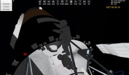
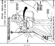
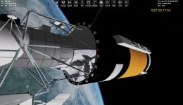
I was thinking another scenario might be the release of the solar array.
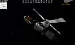
Skylab2.


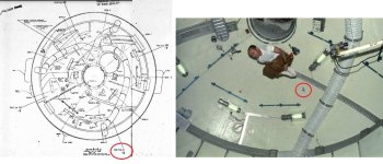
So the scenario set up use the Rendezvous with Skylab 2 scenario, No array, parasol deployed.

Set the timing to 07.06.1973, 15:2?

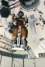
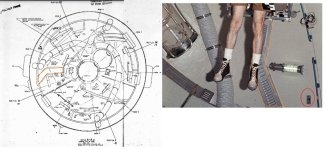
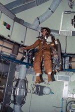
The guy would be out of the airlock already and in his hand the bolt cutter pole ( this would be a vessel attached to his hand)

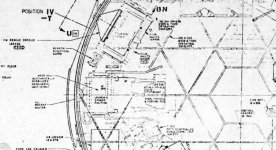
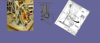
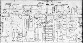
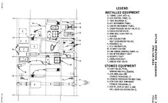
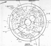
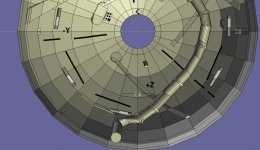
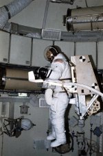
On Skylab I The mass measuring device I have on the 2nd floor. But It really goes on the first floor.

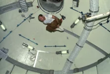
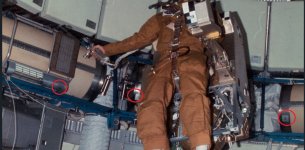
One thing that could be done. Not sure if we want it is have the ASMU be a vessel then you could create an IVA guy to move to it and fly the ASMU inside skylab.
 

Attachments

  • amsu.jpg
    amsu.jpg
    58.8 KB · Views: 13
  • amsu1.jpg
    amsu1.jpg
    55.5 KB · Views: 13
  • skylabnew9.4.1.zip
    skylabnew9.4.1.zip
    114.3 KB · Views: 10
  • 2evaskylab.jpg
    2evaskylab.jpg
    79 KB · Views: 12
Last edited:
This is 1st eva from Skylab with the AMSO Apollo.

I might redo the AMSU inside skylab. Do I make it wear you can flying inside Skylabon the AMSU?
 

Attachments

  • skylabeva2b.jpg
    skylabeva2b.jpg
    57.6 KB · Views: 8
  • skylabeva2c.jpg
    skylabeva2c.jpg
    43.2 KB · Views: 8
Looking at different things.

The ASMU. and next to it as a foot controlled device

I found these videos:
 

Attachments

  • amsuposition1.jpg
    amsuposition1.jpg
    107.9 KB · Views: 2
  • asmu4.jpg
    asmu4.jpg
    68.8 KB · Views: 2
  • asmudonning1.jpg
    asmudonning1.jpg
    92.4 KB · Views: 2
  • asmulocaation2.jpg
    asmulocaation2.jpg
    143.8 KB · Views: 2
  • 10076222.jpg
    10076222.jpg
    43.5 KB · Views: 2
I think these videos are great. Lots of details. I can go and redo the textures to number the tanks, cargo bins,....

Not how much I can/should do. framerate,.......
 
I think these videos are great. Lots of details. I can go and redo the textures to number the tanks, cargo bins,....

Not how much I can/should do. framerate,.......

Well, you shouldn't ask me there, because of SSU, I still have a pretty decent machine for framerate. You can of course optimize a lot for higher framerates, but I think in the beginning, getting functionality is of higher importance.

And you should maybe also consider Checkovs Gun for Orbiter Add-ons there: Details are also features and features must get implemented, tested and deployed/packaged. And that for every release. Less can be more to increase quality. Also some features can be frustrating for the player, for example if you invest 2500 polys into a panel that has no function and could be done as plain texture with a normal map as well.

Also, since Skylab is so big and compartmentalized, you could split the complete visual in Orbiter into smaller parts and display only a subset of the complete mesh you have. For example. if you are in the OWS, why should the airlock and MDM be displayed at full detail and quality? You could easily reduce detail and texture resolution a lot there in that case.
 
Also, since Skylab is so big and compartmentalized, you could split the complete visual in Orbiter into smaller parts and display only a subset of the complete mesh you have. For example. if you are in the OWS, why should the airlock and MDM be displayed at full detail and quality? You could easily reduce detail and texture resolution a lot there in that case.
So have mesh of the MDA/STL, and OWS and airlock module and based off the VC location. you see this mesh,.....
 
So have mesh of the MDA/STL, and OWS and airlock module and based off the VC location. you see this mesh,.....
exactly. Same could be done outside depending on camera position, but that has currently the lowest gain per effort.
 
Thanks. We have access to what the panels look like. So I may start in the airlock. But function is another thing.
 
Thanks. We have access to what the panels look like. So I may start in the airlock. But function is another thing.

Thats always the other thing. Thats why I am eyeing with the modular space station. It never progressed far enough to define how the panels look like precisely, but still has enough content researched to have fun with it.
 
Well I think If I make a cylinder and wrap this texture on it. I should be get the correct door placement,....

And then build this panel and place in there.
 

Attachments

  • evapanel.jpg
    evapanel.jpg
    73.6 KB · Views: 5
  • airlocklayout.jpg
    airlocklayout.jpg
    99.6 KB · Views: 6
And here is why skylab is hurting my brain.

The plan view is looking forward to the dome. But watching the youtube video I notice he had direction markers. And in real life it had them. So I can add those.

BUT looking at the view from the first deck and looking into the dome we get this.

In the image of the dome model Z+ is down But in the model when the ATM rotates the Z+ should be the top?
Wouldn't the left/hand only explain the reversal of the y axis.
 

Attachments

  • z+.webp
    z+.webp
    60.2 KB · Views: 7
  • viewy-.jpg
    viewy-.jpg
    106.8 KB · Views: 7
  • viewaa1.jpg
    viewaa1.jpg
    101.5 KB · Views: 5
  • viewaa.jpg
    viewaa.jpg
    88.9 KB · Views: 5
  • domeviewtop3.jpg
    domeviewtop3.jpg
    99.5 KB · Views: 7
Different coordinate systems....
Thanks. But I know from the view in the MDA in real life. The Z+ is up.
BUt why would the NASA plans and the real life be different.

So in the model looking the same direction as real life Z+ is up, right?


on the shuttle iz Z+ down?

Space Shuttle Body Axis Coordinate System​

The Space Shuttle Body Axis Coordinate System (BACS) is a rotating, right-handed, Cartesian system. The origin of the Space Shuttle BACS is the center of mass of the orbiter. The three axes, X, Y, and Z,are defined as follows:
  • The X axis is parallel to the orbiter structural body X-orbiter axis, and is positive toward the nose.
  • The Z axis is parallel to the orbiter plane of symmetry, is perpendicular to the X axis, and is positive down with respect to the orbiter fuselage.
  • The Y axis completes the right-handed orthogonal system.
The Euler sequence that is commonly associated with this system is a yaw, pitch, roll sequence. This attitude sequence is yaw, pitch, and roll around the Z, Y, and X axes, respectively.
 

Attachments

  • mdafrontview.webp
    mdafrontview.webp
    61.8 KB · Views: 8
What I mean is: Different plans can have different coordinate systems, and thus, can be confusing if you don't know the coordinate system used.

And that also means, that different modules can have different coordinate systems.
 
What I mean is: Different plans can have different coordinate systems, and thus, can be confusing if you don't know the coordinate system used.

And that also means, that different modules can have different coordinate systems.
What a mess. I wonder how would you know which system? If I had no internal then no issues.

There are some for sure things. top is the SAL with Tripod and bottom is the wardrobe.

But between the floors that don't align up. What should be constant is the vents.

The inside of the dome is marked +/- z and y. I assume then that Z+ dome side is up?

Depends. You can usually find a hint in the text about the coordinate systems, but it must not be near the drawing. For example, the coordinate systems used could be explained in the beginning of the report and aren't further explained until the end.
 
Not sure. I can add more details like the numbering of the case,....

The problem with justing showing the airlock and not OWS or MDA if in the airlock is they have view ports and you would see nothing.
 
The problem with justing showing the airlock and not OWS or MDA if in the airlock is they have view ports and you would see nothing.

Just showing one is likely not enough except hatches closed. But again, you can also replace the high-quality meshes with low quality ones then.
 
Redid the dome top. Added numbers on the lights,.....

This is in VB so it is just the dome top
 

Attachments

  • NEWDOME2.jpg
    NEWDOME2.jpg
    55 KB · Views: 8
  • NEWDOME1.jpg
    NEWDOME1.jpg
    60.7 KB · Views: 8
I am working with the guy you did those youtube videos.

Because of changes over time and trainer versus real life. It is hard to say this is what it looks like. For example the water storage tanks. They are numbered. But I have seen images the number is higher up than the middle. And sometimes a wide band at the end,....

The lights are numbered. But the light position changes. Sometimes that are in the middle and sometimes lower.
 

Attachments

  • watertank1.jpg
    watertank1.jpg
    87.8 KB · Views: 6
  • watertank2.jpg
    watertank2.jpg
    102.7 KB · Views: 6
Back
Top