Another thing we probably are going to need for the adapter is its mass. I'll add a ADAPTER_MASS scenario line for the Centaur and associated code next week.
You are using an out of date browser. It may not display this or other websites correctly.
You should upgrade or use an alternative browser.
You should upgrade or use an alternative browser.
Centaur G/G Prime High Energy Upper Stage
- Thread starter DaveS
- Start date
It seems that RL-10 had 2 different types of transducer box used. Which one should I model? Top or bottom?

---------- Post added at 05:00 PM ---------- Previous post was at 03:41 PM ----------
One more question - do we need extended nozzle for that?
---------- Post added at 05:00 PM ---------- Previous post was at 03:41 PM ----------
One more question - do we need extended nozzle for that?
Looking at this picture, from a Centaur G Prime display somewhere, I'd say the top box (with a flat front) is the correct.
- Joined
- Feb 4, 2008
- Messages
- 9,754
- Reaction score
- 1,027
- Points
- 203
Loru: Go with the top and no nozzle extension. The nozzle extension came later, during the 90's and only on the Atlas Centaur. The Centaur G Prime used the Titan IV had no nozzle extensions.

- Joined
- Feb 4, 2008
- Messages
- 9,754
- Reaction score
- 1,027
- Points
- 203


Thanks. I think, I'll simplyfy top of turbopump assembly a bit. It's not visible from any point outside.
Next question: D3d9 allow specular maps so I can pretty much make it as single meshgroup. Inline compatibility would require splitting it into 2-3 groups depending on shine strenght.
What's your take on that?
Next question: D3d9 allow specular maps so I can pretty much make it as single meshgroup. Inline compatibility would require splitting it into 2-3 groups depending on shine strenght.
What's your take on that?
- Joined
- Feb 4, 2008
- Messages
- 9,754
- Reaction score
- 1,027
- Points
- 203
I think keeping it all one group is the best. Some visual enhancement is lost, but I still think that this is the right way to go.Thanks. I think, I'll simplyfy top of turbopump assembly a bit. It's not visible from any point outside.
Next question: D3d9 allow specular maps so I can pretty much make it as single meshgroup. Inline compatibility would require splitting it into 2-3 groups depending on shine strenght.
What's your take on that?

Ok - I've taken some creative liberty for turbopump. Also noticed that on Centaur there is no this second box on the nozzle - do we keep it or throw it?
If we don't know if it's there, I say delete it.
- Joined
- Feb 4, 2008
- Messages
- 9,754
- Reaction score
- 1,027
- Points
- 203
Keep it. I'm pretty sure it's flight hardware.Ok - I've taken some creative liberty for turbopump. Also noticed that on Centaur there is no this second box on the nozzle - do we keep it or throw it?
- Joined
- Feb 4, 2008
- Messages
- 9,754
- Reaction score
- 1,027
- Points
- 203
Looks great! Seems like all that is missing the Gas Generator (GG) exhaust duct.Hmm - some progress. I think I'll call it a day.

---------- Post added at 09:28 PM ---------- Previous post was at 09:13 PM ----------
Nice document on the RL-10: https://webfiles.uci.edu/dbeerer/rockets/RL10.pdf

- Joined
- Feb 4, 2008
- Messages
- 9,754
- Reaction score
- 1,027
- Points
- 203
Even better. Could you add the raised edges to the nozzle bands? The photo GPN-2000-000698.jpg shows them very well. Also, the nozzle interior should be identical to the exterior minus the nozzle bands.and bit more shiny:
Last edited:
Sure
Raised edges on the nozzle bands and nozzle interior will be done same as cooling tubes on the outside (normal map). All I UVW unwrapped so far is engine.
BTW - can you put msh or 3ds of centaur itself for download so I can grab relative positions of fuel tubes?
Raised edges on the nozzle bands and nozzle interior will be done same as cooling tubes on the outside (normal map). All I UVW unwrapped so far is engine.
BTW - can you put msh or 3ds of centaur itself for download so I can grab relative positions of fuel tubes?
- Joined
- Feb 4, 2008
- Messages
- 9,754
- Reaction score
- 1,027
- Points
- 203
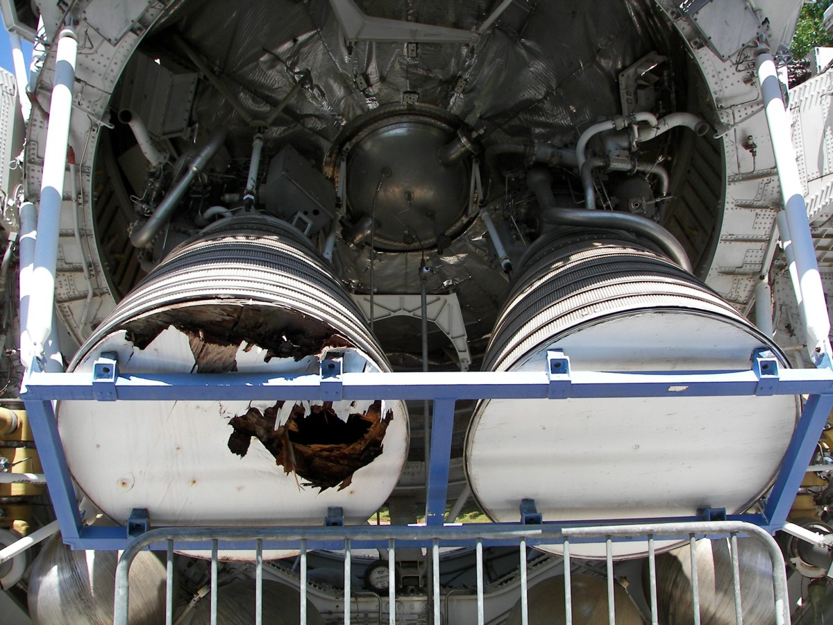
These images show the feedlines. Top Y manifold is LH2 while the bottom is LOX. Diameter of the bulkhead is 120" (3.048 m)Sure
Raised edges on the nozzle bands and nozzle interior will be done same as cooling tubes on the outside (normal map). All I UVW unwrapped so far is engine.
BTW - can you put msh or 3ds of centaur itself for download so I can grab relative positions of fuel tubes?


- Joined
- Feb 6, 2008
- Messages
- 38,965
- Reaction score
- 3,937
- Points
- 203
- Location
- Wolfsburg
- Preferred Pronouns
- Sire
Looks great! Seems like all that is missing the Gas Generator (GG) exhaust duct.
Which GG exhaust duct? The RL-10A is closed expander cycle engine and does not have a gas generator, not even for engine start.
(Interesting reading there about the variations possible for rocket engines:
https://blogs.nasa.gov/J2X/tag/rl10-rocket-engine/
)
Another interesting reading about the RL-10 engine used here:
http://www.ecosimpro.com/download/articles/SpacePropulsion2012_2355411.pdf
The engine starts by "bootstrap cycle": It uses the difference between tank pressure and space to push the propellant through the lines and evaporate a small bit of it by the heat stored in the combustion chamber walls.
No gas generator involved.
What you have are really tiny bleed lines connected to the FCV-1 and FCV-2 valves, which dump some fuel overboard during pre-start for thermal conditioning or during shutdown for reducing pump stress. Both valves are normally open but close if pressure exceeds a fixed threshold.
- Joined
- Feb 4, 2008
- Messages
- 9,754
- Reaction score
- 1,027
- Points
- 203
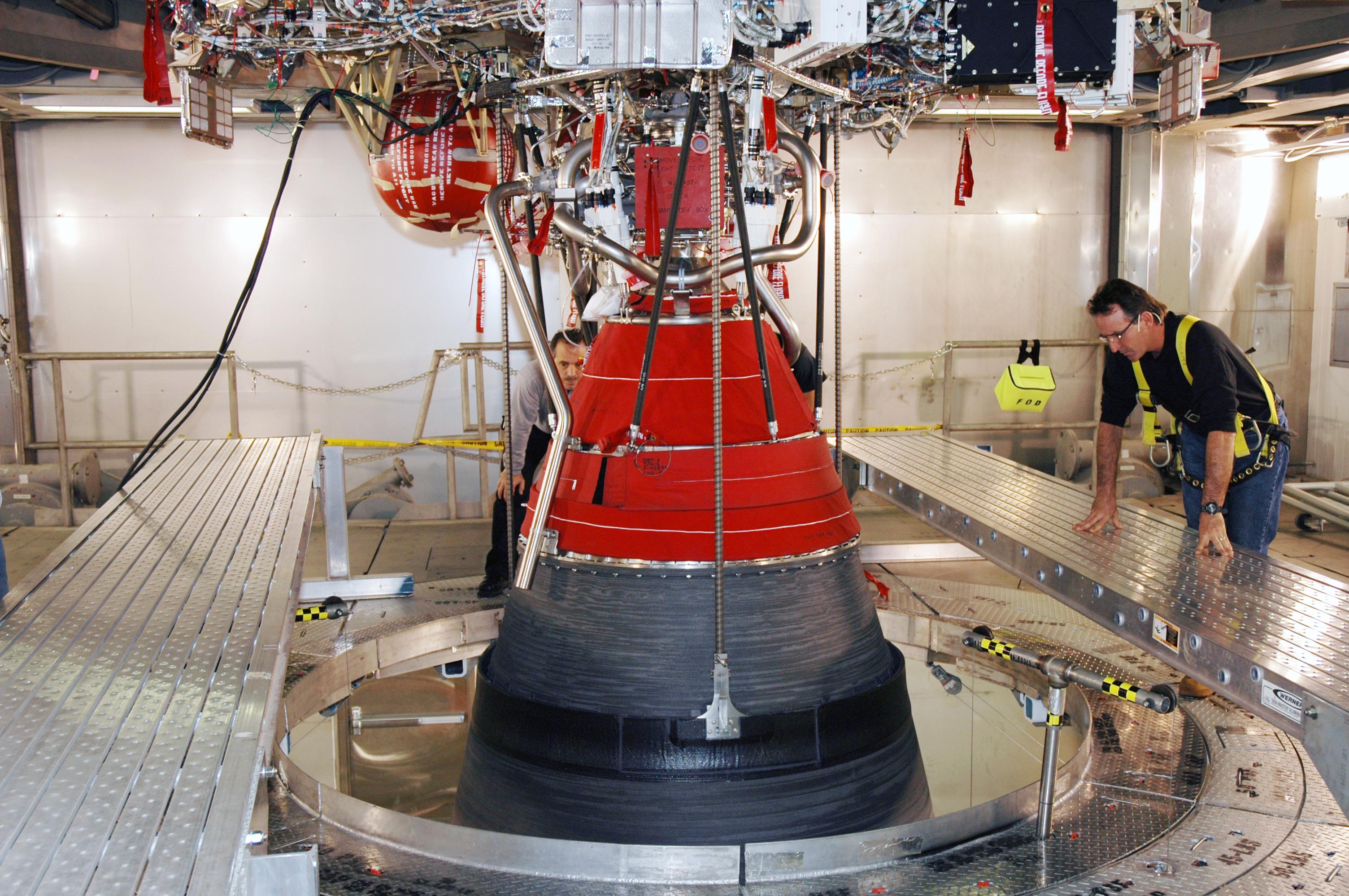
Then what is this:Which GG exhaust duct? The RL-10A is closed expander cycle engine and does not have a gas generator, not even for engine start.
(Interesting reading there about the variations possible for rocket engines:
https://blogs.nasa.gov/J2X/tag/rl10-rocket-engine/
)
Another interesting reading about the RL-10 engine used here:
http://www.ecosimpro.com/download/articles/SpacePropulsion2012_2355411.pdf
The engine starts by "bootstrap cycle": It uses the difference between tank pressure and space to push the propellant through the lines and evaporate a small bit of it by the heat stored in the combustion chamber walls.
No gas generator involved.
What you have are really tiny bleed lines connected to the FCV-1 and FCV-2 valves, which dump some fuel overboard during pre-start for thermal conditioning or during shutdown for reducing pump stress. Both valves are normally open but close if pressure exceeds a fixed threshold.

- Joined
- Feb 6, 2008
- Messages
- 38,965
- Reaction score
- 3,937
- Points
- 203
- Location
- Wolfsburg
- Preferred Pronouns
- Sire
Then what is this:
First of all it looks very Atlas-V Centaur specific, because it seems to be designed to interface with the stage structure and ends at a structural support.

possibly a single vent for both FCVs. this part looks different one a DEC.
on a Delta-IV, RL-10B:
Similar threads
- Replies
- 10
- Views
- 4K
- Replies
- 21
- Views
- 18K
- Replies
- 1
- Views
- 9K
- Replies
- 13
- Views
- 6K