Request UMMU Compatible Helicopter?

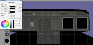
I think I'll cut the door out. On the VC I am using the same mesh. So I doubled all animations so the rotos turn on the vc and external mesh.

I have the main mesh set to always.

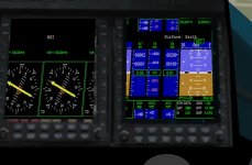
I might could fit a mfd into the screen but not sure if you would be able to read any info off of them.

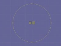
You can show the same mesh in always and VC, no need for duplicating the mesh. But you can add extra mesh data to the visual cockpit by including a mesh that is only visible in MESHVIS_VC. In that mesh, I would put simply rectangles for the MFDs and maybe some of the bigger switches for more perspective.

EDIT: But on the SH-60, the pilot is on the left seat, not on the right.
 
Last edited:
Ok. If I don't duplicate the mesh/animation then when you are in VC mode and go to outside view F1 then you see the main animations working not not the ones on the VC.

If I just did a cockpit not sure what you would see out the back walkway.
 
Ok. If I don't duplicate the mesh/animation then when you are in VC mode and go to outside view F1 then you see the main animations working not not the ones on the VC.

If I just did a cockpit not sure what you would see out the back walkway.

Sounds strange then - did you use the correct mesh index?

BTW, just skimmed the manual to be sure... I was wrong on the SH-60B.. either pilot seat can be used by pilot or copilot, it is just a matter of style.

Thought the right seat had more navigation displays, but no... at least not on the B model. But for the primary USW mission, the left hand seat is the ATO and the right hand seat is the pilot...damn, is that complicated.
 
Last edited:
right now I have 2 separate meshes the main set to always and the vc set to VC. They are the same mesh. So the main mesh is 0 and the other one is 1.

Not sure what it will look like if I make just the cockpit for a VC.
 
right now I have 2 separate meshes the main set to always and the vc set to VC. They are the same mesh. So the main mesh is 0 and the other one is 1.

Not sure what it will look like if I make just the cockpit for a VC.

THEN, you need two animations for VC and main mesh, since one animation only applies to one mesh. Thus I recommend using "MESHVIS_ALWAYS | MESHVIS_VC" as visibility mask on the main mesh. Don't tell me that it does not work. I know it does.
 
Ok so use a entire copter for the main mesh and set it to MESHVIS_ALWAYS | MESHVIS_VC

Then wouldn't I need just 1 set of animations as there is 1 mesh?
 
Ok so use a entire copter for the main mesh and set it to MESHVIS_ALWAYS | MESHVIS_VC

Then wouldn't I need just 1 set of animations as there is 1 mesh?

Exactly. Either you need one animation per mesh or one mesh.

If you would have time to be smart, you could of course try breaking down the mesh into multiple sections and animate them separately, and of course also have custom visibility settings for each of them.
 
I think will just use 1 mesh for the main and VC.

Not sure if using the 1 mesh if I can put the MFD's in. In some ways a 2d panel might be good so you could see the MFd's?
 
I think will just use 1 mesh for the main and VC.

Not sure if using the 1 mesh if I can put the MFD's in. In some ways a 2d panel might be good so you could see the MFd's?

You can still make a mesh that contains only the rectangles for the VC MFDs and make it MESHVIS_VC, adding it additionally to the main mesh. Make it float a few mm above the panel and you are fine from Z-order problems.
 
OK I added 2 black rectangles for the 2 MFD's. Not sure if I want the HUD as one of the screens. But when I switch to VC all I see are the 2 black rectangles. The MFD are turned on. Am sure I got the right groups

Code:
bool NH90::clbkLoadVC(int id)
{
 VCHUDSPEC hud;
 VCMFDSPEC mfd;
 
 //Virtual cockpit elements
 if((id>=0)&&(id<1)){
  if(id==0){
   SetCameraDefaultDirection(_V(0,0,1));
   SetCameraOffset(_V(.48,-1.1,4.1));
   SetCameraShiftRange(_V(0,0,0.1),_V(-0.2,0,0),_V(0.2,0,0));
   oapiVCSetNeighbours(-1,-1,-1,-1);

   //hud.nmesh=0;
   //hud.ngroup=-1;
   //hud.hudcnt=_V(0,0,0);
   //hud.size=0;
   //oapiVCRegisterHUD(&hud);
   mfd.ngroup=275;
   mfd.nmesh=0;
   oapiVCRegisterMFD(0,&mfd);
   mfd.ngroup=274;
   mfd.nmesh=0;
   oapiVCRegisterMFD(1,&mfd);
  }
 }
 return 1;
}
 
Did you make sure that the rectangles also have texture coordinates, but no texture assigned?
 
This is what I have. material MFD is just a black material no texture assigned.

Should I have one in the center for the HUD?
 

Attachments

  • nh90mfd.jpg
    nh90mfd.jpg
    79.9 KB · Views: 9
Either that (and later remove the texture) or good old classic manual editing of the mesh file. Or editing my export script, but that is a bit more complicated, since you need to remove texture and texture reference for the meshgroup, but keep UV coordinates.
 
Shouldn't I be able to put the MFD on the black rectangles and move them in front of the existing mesh?

And maybe put one in the center as the HUD?
 
Shouldn't I be able to put the MFD on the black rectangles and move them in front of the existing mesh?

And maybe put one in the center as the HUD?

For displaying the MFD on the black rectangles, the black rectangles need texture coordinates for every vertice, otherwise it is pretty futile.

Also, better make the material bright white... Or you will get a dark black display. ;)
 
So I need to make a blank texture and then white
*******
Got it I need to align the textures though.

On the landing gear light. I have it as red and green. Which shown red be gear up or gear down

It looks like the texture should be right.

but when I run it I get this. Is there a texture that you can see when appling it to the mesh.
 

Attachments

  • MFDTEX.jpg
    MFDTEX.jpg
    26.4 KB · Views: 11
  • MFDTEX1.jpg
    MFDTEX1.jpg
    52.1 KB · Views: 21
Last edited:
I wonder if you could attach a UMMU and use their HUD. But you wouldn't be able to control the copter without switching.
 
Back
Top