The Universal Flight Simulator

Maybe the holes are for LEDs.
That's what my initial thought was. But I can't see how one supposed to wire them, cause the hole itself is blind and there is no space for wires (see pictures attached).
I ended up with printing plugs with locating pin, which has a snug fit even without applying glue.
That method of filling with PVA is failed by the way :) To soft and no adhesion with surface.

Maybe the color is what they could buy cheap this week. Probably intended to be painted in the end product.
Haha, maybe it is the case with those soviet switches – don’t get me wrong, they are mil-spec, built like a brick dunny, but that inconsistency with them colours man..:LOL:
 

Attachments

  • 001.jpg
    001.jpg
    28.3 KB · Views: 7
  • 002.jpg
    002.jpg
    36.2 KB · Views: 6
  • 003.jpg
    003.jpg
    7.6 KB · Views: 6
Hey guys,

Progress report 2024-W23:

  1. All MFD button caps are removed from switch assemblies and installed in custom fixture for painting.
  2. 2mm glass was cut to size to fit fuel indicator to protect LCD panel. Process of making other 3x glasses for 3x MFD is underway.
PS. The glass is dirty for a time being and will be cleaned after final assembly of the indicator.
Little note regarding painting – as I paint everything outside, I rely on good weather, which doesn’t want to cooperate for last 2x weeks or so here in the S-E UK.. haha
 

Attachments

  • 01.jpg
    01.jpg
    107.6 KB · Views: 4
  • 02.jpg
    02.jpg
    104.4 KB · Views: 5
Last edited:
Hi all,


Progress report 2024-W24:
1. Protection glass is cut for both 10" AMFDs.
2. Most of MFD parts are ready for spray paint.
3. Prototyping for MFD button insects is finished. Printing and sanding are ongoing.

PS. Also I've scored a real HUD unit from Tornado GR4 aircraft on Ebay. It misses couple of side cover plates and combiner glass with front panel.
Internally it is a complete unit (both optically and mechanically).
Recreating missing part should not be a problem, even a combiner is doable. Far easier than reverse engineering the beast.. 😊
Attached couple of ebay listing photos - because I've disassembled it straight after arriving due to its size (almost 2ft long) and weight (around 15kg) haha

There are 2x ways of making it work again:
  1. Reverse engineering the CRT circuit and feed a composite signal from Raspberry (preferable!).
  2. Removing the CRT assy all together and use off-the-shelf LCD with high brightness LED for its backlight (plan B).
 

Attachments

  • 01.png
    01.png
    516.2 KB · Views: 12
  • 02.png
    02.png
    427.8 KB · Views: 12
  • 03.png
    03.png
    484.8 KB · Views: 11
  • 04.png
    04.png
    570.5 KB · Views: 12
  • 05.png
    05.png
    789.5 KB · Views: 12
  • 06.png
    06.png
    698.2 KB · Views: 12
Last edited:
Hi guys,

Progress report 2024-W25:
  1. Panting of different parts is underway.
  2. Both 10” MFD and 4” indicator screen assemblies are finished with protective 2mm glass installed.
  3. Reverse engineering of the HUD is started (creating a simplified 3d model to insure proper interface between the unit and panel structure).

Little note about those button caps – I’ve spent a lot of time trying to make them look good.
They went thru following procedures:
  1. 84 pcs. of small end caps were 3d printed and installed.
  2. Each of them was sanded flush.
  3. 2x coats of primer were applied.
  4. Then I took white wax stick and filled all imperfections .
  5. 2x coats of spray silver paint were applied.
Now I’m thinking of painting them black actually and rub down white wax into that dash line to make it standout.. Will see haha
 

Attachments

  • 01.jpg
    01.jpg
    100.8 KB · Views: 11
  • 02.jpg
    02.jpg
    89.6 KB · Views: 10
  • 03.jpg
    03.jpg
    71.3 KB · Views: 10
  • 04.jpg
    04.jpg
    111.2 KB · Views: 11
  • 05.jpg
    05.jpg
    58.6 KB · Views: 11
Just very very crude test of mirror and collimating lens:
Static image source – Phone’s LCD (at full brightness).
Combiner – plain 2mm float glass for picture frames.

Looks very cool already, but sooo far from the the final product.. haha
 

Attachments

  • 01.jpg
    01.jpg
    108.6 KB · Views: 29
  • 02.jpg
    02.jpg
    37.5 KB · Views: 29
Last edited:
Hi guys,

Progress report 2024-W26:
  1. 88x MFD’s and fuel indicator’s buttons have been painted black and filled with white wax to provide visible markings. Some paint defects were corrected with black marker. Ready for a clear coat application.
  2. 3D model of the HUD unit is complete. Designing and printing of missing side covers is underway. Due to their complex shapes several test articles were printed to ensure a proper geometry and fixing holes alignment.
  3. Prototyping of the combiner assembly is underway as can be seen from 3D model screengrabs.
  4. All MFDs back enclosures were primed and painted.
 

Attachments

  • 01.jpg
    01.jpg
    88.1 KB · Views: 4
  • 02.jpg
    02.jpg
    68.7 KB · Views: 6
  • 03.jpg
    03.jpg
    86.4 KB · Views: 5
  • 04.jpg
    04.jpg
    43.5 KB · Views: 5
  • 05.jpg
    05.jpg
    57.9 KB · Views: 6
  • 06.jpg
    06.jpg
    60.7 KB · Views: 6
  • 07.jpg
    07.jpg
    67.8 KB · Views: 6
  • 08.jpg
    08.jpg
    55.2 KB · Views: 5
  • 09.jpg
    09.jpg
    75.2 KB · Views: 5
  • 10.jpg
    10.jpg
    103.2 KB · Views: 5
Hi guys,

Progress report 2024-W27:

  1. Design of new MFD button cover lids is finished. All new part are printed and test fitted.
  2. Painting of MFD buttons and button cover lids are complete.
  3. Assembly of the fuel quantity indicator is finished.
 

Attachments

  • 01.jpg
    01.jpg
    104.4 KB · Views: 5
  • 03.jpg
    03.jpg
    109 KB · Views: 5
  • 02.jpg
    02.jpg
    103.7 KB · Views: 5
  • 04.jpg
    04.jpg
    96 KB · Views: 5
  • 05.jpg
    05.jpg
    69.9 KB · Views: 5
  • 06.jpg
    06.jpg
    46.3 KB · Views: 4
  • 07.jpg
    07.jpg
    73.5 KB · Views: 5
Hi guys,

Progress report 2024-W28:
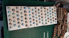
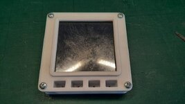
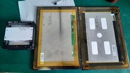
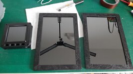
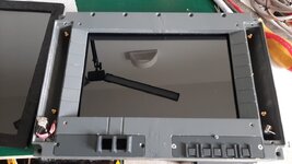
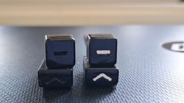
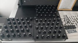
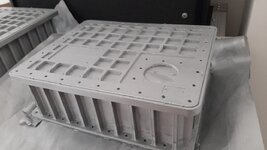
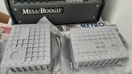
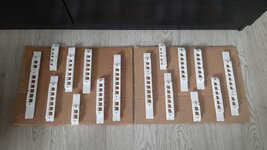
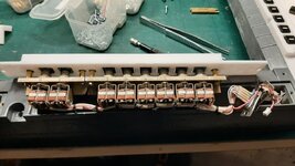
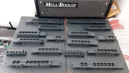
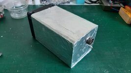
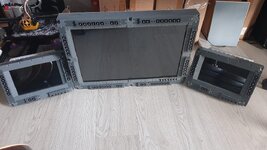
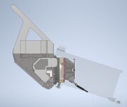
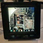
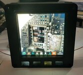
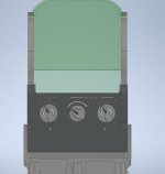
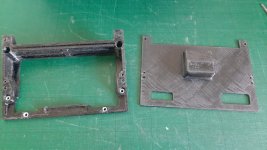
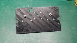
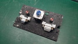
  1. MFD buttons and corresponding lids are finished.
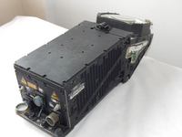
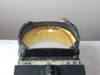
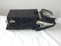
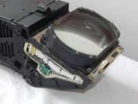
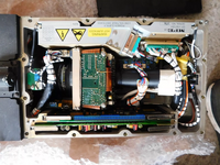
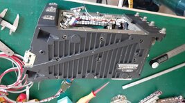
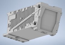
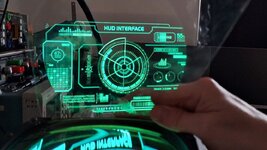
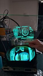
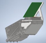
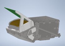
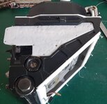
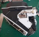
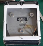
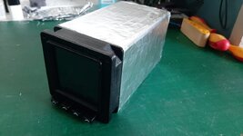
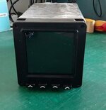
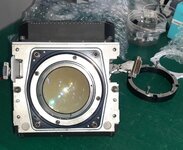
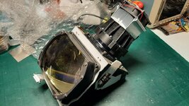
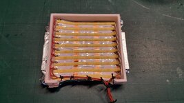
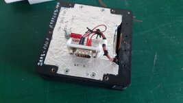
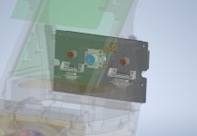
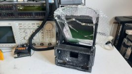
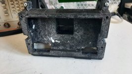
  2. Circuit reverse engineering of the HUD unit has been started. Tracing of input EMI filter is complete. Low voltage power supply is underway.
The only 2x things left to finish those MFDs hardware-wise are creating ID plates and gluing some blue velcro all around front bezels and then fun of programming them begins haha


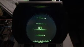
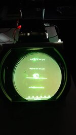
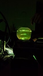
Regarding reverse engineering the HUD - I've managed to figure out supply voltages - there are as follows:
1) 200 VAC, 400Hz, 3 ph (!) - main AC supply.
2) 115 VAC, 400Hz, 1 ph - front control panel backlight supply (not required in my design) – typical backlight voltage for Tornados.
3) +28 VDC - DC main supply.

Funny thing about that 3phase AC line - there are no motors inside, it only passes EMI filters and hits a bridge rectifier brick right off the bat after.. haha
I guess this design decision was made because 200VAC/3ph is the primary supply bus in Tornado aircraft.
After the rectifier it’s converted to 200*1.35 = +270 VDC, so now I'm looking for a nice way to re-produce this voltage via different dc-dc converters.

BTW, all those 200/115VAC lines are supplied via typical d-sub connectors :)

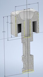
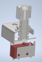
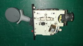
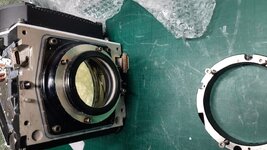
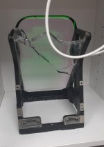
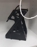
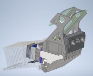
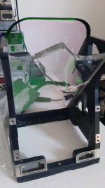
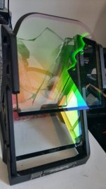
PS. I haven’t taken any photos of assembled gear lever, I went straight into business and removed enclosure for “inspection”.. lol
It looks like this:
https://forum.dcs.world/uploads/mon...C4.jpeg.4434fcee52f2bf859de43d5fe1ba88b7.jpeg
 

Attachments

  • Landing gear switch 02.jpeg.jpg
    Landing gear switch 02.jpeg.jpg
    121.3 KB · Views: 8
  • 001.jpg
    001.jpg
    122.1 KB · Views: 8
Morning all,


Progress report 2024-W29:

Work on the Hud unit continues.

I’ve decided to design all electronics myself instead of bringing existing circuits back to live.
Main issues of reverse-engineering this beast are custom chips for which I cannot find any info, let alone pinouts or datasheets.
The current game plan is to adopt 4” inch LCD (the same model I’ve used in my fuel quantity indicator) to the existing optics with stock backlight removed. 12V 100W LED chip is considered as a light source for LCD backlight to provide enough display brightness making HUD image visible at direct sunlight.
 

Attachments

  • First lens and display interface 02.jpg
    First lens and display interface 02.jpg
    93.7 KB · Views: 7
  • First lens and display interface.jpg
    First lens and display interface.jpg
    131.1 KB · Views: 6
  • First lens and display interface 03.jpg
    First lens and display interface 03.jpg
    90.3 KB · Views: 6
  • Original vs custom diplay adapter.jpg
    Original vs custom diplay adapter.jpg
    156.8 KB · Views: 9
  • Custom image and light source design.jpg
    Custom image and light source design.jpg
    53.7 KB · Views: 9
  • Custom image and light source design 02.jpg
    Custom image and light source design 02.jpg
    28.5 KB · Views: 8
Last edited:
Hi guys,

There was no major progress during 30th week - I was on my annual leave visiting Edinburgh (hail to all Scottish Orbinauts here! 😊 )
I'm still waiting for parts coming from China (led chip and heatsink, hopefully they will be here today-tomorrow).
No sim related photos attached lol
 

Attachments

  • 01.jpg
    01.jpg
    198.8 KB · Views: 9
  • 02.jpg
    02.jpg
    127.2 KB · Views: 9
  • 03.jpg
    03.jpg
    142.4 KB · Views: 9
Hi guys,

Progress report 2024-W31:

  1. Parts for HUD projector are received from China.
  2. Initial prototype of custom LCD backlight system is finished and tested satisfactory. There are no visible “hot spots”.
  3. Painting is done. Inner part of the reflector is covered with aluminium foil (no shown on pictures)
LCD panel ended up very bright as it supposed to be. In fact, so bright that my phone’s camera couldn’t focus properly, hence all those blurry images.. In real live all markings and text look very sharp and visible both in dark and in broad daylight.

Getting there! 😊
 

Attachments

  • Test fit with collimating assy.jpg
    Test fit with collimating assy.jpg
    132.2 KB · Views: 11
  • Look into collimating lens (display in night mode).jpg
    Look into collimating lens (display in night mode).jpg
    33.8 KB · Views: 11
  • Look into collimating lens (display in day mode).jpg
    Look into collimating lens (display in day mode).jpg
    21.5 KB · Views: 10
  • Look thru combiner (2mm float glass).jpg
    Look thru combiner (2mm float glass).jpg
    16.9 KB · Views: 11
  • Painted and assembles.jpg
    Painted and assembles.jpg
    37.6 KB · Views: 11
  • 4'' LCD panel with custom 3mm defuser.jpg
    4'' LCD panel with custom 3mm defuser.jpg
    102.1 KB · Views: 12
  • Reflector and 1st lens + main LED assy 02.jpg
    Reflector and 1st lens + main LED assy 02.jpg
    76.7 KB · Views: 12
  • Reflector and 1st lens + main LED assy 01.jpg
    Reflector and 1st lens + main LED assy 01.jpg
    42.2 KB · Views: 12
  • Reflector and 1st lens 02.jpg
    Reflector and 1st lens 02.jpg
    66.8 KB · Views: 11
  • Reflector and 1st lens 01.jpg
    Reflector and 1st lens 01.jpg
    72.2 KB · Views: 11
Hi guys,

Progress report 2024-W32:
  1. After playing with custom backlight for HUD LCD I’ve decided to upgrade backlight assembly of 4” fuel indicator and 10” MFDs as well. The main issued with those Chinese displays is a lack of nice an even backlight, causing the panel looks quite dim even at full brightness.
  2. Custom backlight assy for 4” fuel indicator is finished and tested.
  3. Custom backlight assy for 10” MFDs is under way.
 

Attachments

  • 01-Fuel indicator LCD panel and new backlight assy.jpg
    01-Fuel indicator LCD panel and new backlight assy.jpg
    108.7 KB · Views: 8
  • 02-Fuel indicator new backlight assy.jpg
    02-Fuel indicator new backlight assy.jpg
    124.4 KB · Views: 7
  • 03-Fuel indicator LCD assy A101003-100 with backlight connector.jpg
    03-Fuel indicator LCD assy A101003-100 with backlight connector.jpg
    96.1 KB · Views: 8
  • 04-Fuel indicator LCD medium brightness.jpg
    04-Fuel indicator LCD medium brightness.jpg
    67.6 KB · Views: 8
  • 05-Fuel indicator LCD full brightness.jpg
    05-Fuel indicator LCD full brightness.jpg
    69 KB · Views: 10
  • 06-10'' MFD new backlight assy WIP.jpg
    06-10'' MFD new backlight assy WIP.jpg
    89.4 KB · Views: 10
Hi all,

Progress report 2024-W33:
  1. Custom Backlight assembly is finished.
  2. 1 of 2 10” MFDs is assembled back and fully tested.
 

Attachments

  • Led assembly.jpg
    Led assembly.jpg
    112 KB · Views: 7
  • Display assembly.jpg
    Display assembly.jpg
    79.4 KB · Views: 7
  • Display assembly fully connected.jpg
    Display assembly fully connected.jpg
    115.6 KB · Views: 6
Last edited:
Hey guys,

Progress report 2024-W35:

1) Missing Combiner assembly is acquired from Ebay. Larger glass is broken but can serve as a template for ordering a substitute made an ordinary float glass.
Currently the broken article can serve as a good test piece providing a benchmark performance.

Small 2nd glass is intact.

The glass itself is quite special. 8.3 mm thick, pilot's side had a special coating which reflects only certain green light wavelength (matching CRT's phosphor colour). Outer side has different coating with high rate of reflexivity with some gold tint in it (couldn't catch it on the camera). See some pictures enclosed. As always, it is hard to capture all those optical marvels on a camera phone haha

Also having this assembly on hand, I can proceed with front panel design, which mounts to the casting.
 

Attachments

  • Combiner assy front.jpg
    Combiner assy front.jpg
    28.3 KB · Views: 6
  • Combiner assy side.jpg
    Combiner assy side.jpg
    22.6 KB · Views: 4
Hey guys,
Progress report 2024-W36:
  1. 3D modelling of combiner assemble is finished.
  2. HUD’s front control panel design is underway.
Also I’ve manages to acquire 506m of triple core shielded PTFE cable from Ebay really cheap (weights a ton!).
This cable will be used for connecting potentiometers of the control system to coresponding ADCs
 

Attachments

  • Updated 3D model.jpg
    Updated 3D model.jpg
    46.4 KB · Views: 5
  • CABLE 01.jpg
    CABLE 01.jpg
    99.1 KB · Views: 5
  • CABLE 02.jpg
    CABLE 02.jpg
    77.5 KB · Views: 5
Hey guys,
Progress report 2024-W37:

  1. Major progress on HUD front control panel design, including controls layout.
  2. Interface adapter was design, printed and tested.
  3. Front panel backplane was 3d printed for testing and fitting proposes. Final article is planned to be laser cut 3mm acrylic.

Also, I’ve managed to capture those weird and wonderful colours reflecting by combiner glass coatings.. it’s amazing, innit? 😊
 

Attachments

  • HUD front panel 3D iso.jpg
    HUD front panel 3D iso.jpg
    50.7 KB · Views: 7
  • HUD front panel 3D front.jpg
    HUD front panel 3D front.jpg
    24.5 KB · Views: 7
  • HUD front panel 3D back.jpg
    HUD front panel 3D back.jpg
    45.2 KB · Views: 8
  • Interface adapter 01.jpg
    Interface adapter 01.jpg
    113.8 KB · Views: 9
  • HUD front panel interface adapter 01.jpg
    HUD front panel interface adapter 01.jpg
    117.9 KB · Views: 9
  • HUD front panel interface adapter 02.jpg
    HUD front panel interface adapter 02.jpg
    126.6 KB · Views: 9
  • HUD Front panal mounting plate front.jpg
    HUD Front panal mounting plate front.jpg
    169.9 KB · Views: 7
  • HUD Front panal mounting plate back.jpg.jpg
    HUD Front panal mounting plate back.jpg.jpg
    149.7 KB · Views: 7
  • Combiner front.jpg
    Combiner front.jpg
    39 KB · Views: 7
  • Combiner back.jpg
    Combiner back.jpg
    35.6 KB · Views: 5
I've found some information regarding glass coatings, really interesting:

These glasses use another technique of a special multi-layer coating called rugate technology. Rugates act like a single inhomogeneous film with a refractive index that varies continuously and periodically throughout the thin-film structure. The same impressive increase in transmission and reflection can be achieved as the ‘holographic’ system but without the bulk of the glass sandwich. Omitec originally developed thin-film rugate technology to manufacture "notch" filters of specific bandwidth. In 1991 flight tests of Head Up Displays, fitted with what was claimed to be the world's first airborne thin-film colour-selective graded combiners were commenced in a Harrier GR.7 and a Tornado GR.4 later in the year. Omitec also delivered Rugate coated Combiners to GEC Ferranti for the wide-angle HUD for the Royal Air Force's Tornado GR.4 mid-life upgrade.

Source - https://rochesteravionicarchives.co.uk/items/tornado-hud-dual-combiner-assembly
 
The Rochester Avionics Site is really a treasure trove!
 
Back
Top