New Release Interplanetary Modular Spacecraft RC9

Build vessel with food, water and oxygen

Thank you very much for this addon. It makes the already very entertaining Orbiter simulation so much more interesting for me!

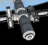
I have troubles constructing a vessel with working life support systems. I have been trying to re-build PeterRoss's vessel from post #164 with following parts (among others):

  • BM201 Command Module
  • BM012 Life Support
  • Radiator 64 (for BM201 Command Module)
  • Radiator 64 (for BM012 Life Support)
  • 2 SolarArrayCirc_7m

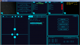
Yet, after unsealing attaching, integrating the parts and adding two dummy crew members the 'System' MFC warns me that all food, oxygen and water are depleted.
Likewise, the 'Life Support' MFC does not display any food, water or oxygen present on the vessel.
The Command Module and Life Support Module are online in the Power management screen of IMS and have enough power to operate.

Could you please help me understand what I have done wrong and what minimum parts I need to construct a vessel which can sustain crew?
 

Attachments

  • ims.png
    ims.png
    154.7 KB · Views: 25
Likewise, the 'Life Support' MFC does not display any food, water or oxygen present on the vessel.

You have added the means to regenerate food, water and oxygen on board. You have not added any actual food, water or oxygen ;)

You'll need storage modules for that. And then you have to fill them, since usually they come empty. Easiest (cheating) way to fill them is to open the scenario editor and fill up propellant resources 1, 2 and 3 (after you added some storage, or maybe your CM has some limited storage built in), since IMS uses propellant resources to manage its consumables for easier accesability.
 
Thank jedidia, I think I just figured out by reading the modders guide that I only had added equipment to regenerate the consumables but not the consumables themselves.
I have not found out thought how to fill the consumable containers, thanks for your tip with the scenario editor.

I have another question regarding said LifeSupport Module: it's battery is not added to the vessel's total capacity; i. e. the Command Module has a battery capacity of 110 and the Life Support Module has 55 but the Power screen only displays the Command Module's 110.

What is the reason for this?
 
Hmmm, don't remember if batteries are assumed to be charged or not on integration... if not, that would explain it. Have a look at the specs menu, it should list the total battery capacity somewhere. If that is ok, then the battery simply needs to charge. If not, maybe something's wrong with the config. I don't have the configs on my laptop, so I can't check right now.
 
The Specs also say the capacity is 110 kWh.

Those are the IMS specific config parameters of the Life Support Module:
Code:
; ======================================
; IMS specific parameters
; ======================================
Name = LifeSupport
ModuleType = Lifesupport
Oxygen = 4
Water = 4
CoolingCapacity = 10000
PowerInput = 3500
Battery = 55
OptimalTemperature = 290
MinTemperature = 275
MaxTemperature = 350

I think the line
Code:
Battery = 55
should be
Code:
BatteryCapacity = 55
right?

Its certainly possible, although I havent looked at the config guide yet, so I cant say. Most of the existing configs have worked fine for me so far though, so Im not sure.

Jedidia, I was hoping that you could help me diagnose a recurring issue that Ive seen both in 2.0 and 2.3. Back a little while ago I posted about my Odyssey station causing CTDs while overloaded. While flying the Altair in the UPS andromeda system, I experienced the exact same issue with my Orbital Shipyards, a CTD that happened at the exact same time in the scenario, but was averted by deleting the Orbital Shipyards from the scenario.

Im puzzled by the behaviour of this glitch, is it possible that some variable for the overall vessel is overloading? (overrunning the numerical constraints of its type)
 
Waste heat calculation for chemical engines

Okay, the fun continues with waste heat calculations:

I think I got the calculation for the required radiator surface for my command module right (as described in the Waste heat calculation section of the design article)

Optimal temperature of the command module: 300 K
Power Input = 10,000 W
=> Radiaton = 5,67*10^-8*(300*0,9)^4 = 301.33 W
=> Waste heat = 10,000 W
=> Required radiator area = 1000 W / 301.33 W = 33.19 m^2

33.19 m^2 radiator surface under optimal conditions seems reasonable for the command module.


My calculation for the chemical sidemount engine seems to be wrong though:
Thrust: 275,000 N
ISP: 4250 m/s
Efficiency: 95

Now, do I have to calculate the thrust power and waste heat exactly as shown in the design guide without any brackets in the formula?

Engines (chemical and thermal):
Engine thrust power is in Watts is approximated as by IMS as:
thPower(W) = thrust * isp / 2
This gives you what the engine spits out! To get the waste heat, take this value and use the same equation as you use for generators:
WasteHeat = thPower(W) / efficiency * 100 - thPower(W)

This would result in
=> Thrust power = (275,000 N * 4250 m/s) / 2 = 584,375,000 W
=> Waste heat = = 584,375,000 W / 95 * 100 - 584,375,000 W = 30756578.95 W
=> Required radiator area = 30756578.95 W / 584,375,000 W = 0.05 m^2

0.05 m^2 can't be correct. Could you give me a hint please on how to calculate this correctly?


Finally, how do I know what capacity my MCS needs to have? Is it the sum of all modules waste heat excluding modules with inbuilt cooling system?
 
Correct me if I'm wrong, but here are my calculations :

Command Module
Radiation : 459.27W/m²
Waste heat : 10000W
Radiator surface : 21.77m²

Sidemount engine (optimal temperature is 700K)
Radiation : 13613.67W/m²
Waste heat : 30756578.95W
Radiator surface : 2 259.24m²
Not relevant to add radiators for this kind of engine IMHO. Just let them cooling down between 2 burns.
---------Edit----------
You should update your engines config file according to PeterRoss'fix (http://www.orbiter-forum.com/showthread.php?p=402359&postcount=251)

Sidemount engine efficiency is changed to 99.9999, so you'd have :
Waste heat : 584.38W
Radiator surface : 0.04m²
Definitely no need for radiator.
-----------------------

Finally, how do I know what capacity my MCS needs to have? Is it the sum of all modules waste heat excluding modules with inbuilt cooling system?
It is the sum of all modules waste heat including modules with inbuilt cooling system.
---------Edit----------
However, do no connect modules with a big difference in optimal temperature to the same radiators (for instance hab module and fission reactor).
-----------------------

Happy orbiting with IMS vessels.
:cheers:
 
Last edited:

I think so, yes.

Now, do I have to calculate the thrust power and waste heat exactly as shown in the design guide without any brackets in the formula?

No, the equation is fine as it is. However, you don't get required radiator area by dividing the waste heat by the thrust power. You get required area by dividing waste heat by radiative capacity per square meter at operating temperature, as you did in your first operation for the CM ;)

That said, these look like the outdated config files. I put in too low efficiency for chemical thrusters, forgetting that they get rid of their heat in the exhaust and only have a rather slow heat buildup. Feel free to increase the efficiency to some 99.9% and forget about the radiators for the thruster.

Finally, how do I know what capacity my MCS needs to have? Is it the sum of all modules waste heat excluding modules with inbuilt cooling system?

Yes, except for life support modules. Since their cooling system IS the MCS, they obviously have to cool themselves by it.

It is the sum of all modules waste heat including modules with inbuilt cooling system.

No. Your nuclear reactor and your engines don't go into the MCS, that would just produce a space-based pressure cooker... :shifty:

I think the required MCS capacity should also show somewhere in the specs.
 
Thanks Furet, I installed the patches you suggested.

Could you tell me how you calculated your results? I cannot see where the difference is just by looking at the results.

Not relevant to add radiators for this kind of engine IMHO. Just let them cooling down between 2 burns.
Mh, I have four of those engines in my current test vessel and they overheat after ten seconds at the latest even at 50% thrust.
 
Mh, I have four of those engines in my current test vessel and they overheat after ten seconds at the latest even at 50% thrust.

Yes, this comment is for the unpatched engines, but it should be OK with patched engines (efficiency 99.9999 as Jedidia pointed out).

Detailed calculation:

Command Module (with optimal temp. 300K)
Radiation : sk*T^4*e = 5.67*10^-8*300^4*1 = 459.27W/m²
Waste heat : 10000W
Radiator surface : 10000/459.27 = 21.77m²

Sidemount engine (with optimal temp. 700K and eff. 99.9999)
Radiation : sk*T^4*e = 5.67*10^-8*700^4*1 = 13,613.67W/m²
ThP : Thrust*ISP/2 = 275000*4250/2 = 584,375,000W
Waste heat : (ThP/Eff*100)-ThP = 584.38W
Radiator surface : 584.38/13,613.67 = 0.04m²

No. Your nuclear reactor and your engines don't go into the MCS, that would just produce a space-based pressure cooker... :shifty:

Thanks Jedidia. I confused betwen MCS and radiator.
 
Last edited:
Ah yes. This makes more sense than my calculations.

Thank you!
 
Jedidia, I was hoping that you could help me diagnose a recurring issue that Ive seen both in 2.0 and 2.3. Back a little while ago I posted about my Odyssey station causing CTDs while overloaded. While flying the Altair in the UPS andromeda system, I experienced the exact same issue with my Orbital Shipyards, a CTD that happened at the exact same time in the scenario, but was averted by deleting the Orbital Shipyards from the scenario.

That's not enough data by far... especially since I can't make head and toes of it.
Let me see if I got this right: You expierienced a ctd under certain circumstances in the past. Now you're having a new scenario, with an IMS station, called "orbital shipyards", that is producing a ctd under the same circumstances. Removing the IMS station from the scenario file removed the CTD.

I am not sure from your posting if "certain circumstances" is a situation, or an exact time after scenario launch, that was identical in the first and the second case. If the second case applies, that should be quite an interesting bug, that can likely only be found by plugging a debugging dll into orbiter and running it from visual studio. You are currently better equiped to do that than I, I don't even have a working setup on my machine currently.

If the first case applies, the first logical thing would be to identify commonalities between the two vessels that caused the ctd, and trying to build a minimal configuration that causes it. Trying to plug it into the debugger might wield a good result, or it might not, depending on where the crash happens (memory leaks have the unfortunate problem to cause crashes in completely unrelated code. A blatant leak is not in the code, I checked that with an instrumentation library, but that doesn't register unallowed memory access, so the possibility of an out-of-bounds operation still exists).
 
BT201's rotating during integration

I line up my BT201's just the way I want them, but when I push the integrate button, I get a "Successful Undocking" message instead of the "Successful Integration" message and well... the photo shows the results.

BT201 on the left is pre-integration, one on the right is post-integration.

What did I forget to do?
 

Attachments

  • TwistedIMS-Integration.jpg
    TwistedIMS-Integration.jpg
    66.9 KB · Views: 24
I line up my BT201's just the way I want them, but when I push the integrate button, I get a "Successful Undocking" message instead of the "Successful Integration" message and well... the photo shows the results.

BT201 on the left is pre-integration, one on the right is post-integration.

What did I forget to do?
Answered here.
 
Can the SSBB parts be grappled with the stock Space Shuttle Atlantis RMS?

I attached a BM201_CONTROL_MODULE to the payload bay of Atlantis but cannot grapple it with the RMS although the blue arrow of the RMS and the red arrow of the BM201 seem perfectly aligned.

Do I have to change something in the BM201's config file?
 
Can the SSBB parts be grappled with the stock Space Shuttle Atlantis RMS?

I attached a BM201_CONTROL_MODULE to the payload bay of Atlantis but cannot grapple it with the RMS although the blue arrow of the RMS and the red arrow of the BM201 seem perfectly aligned.

I have absolutely no idea. If they were originally, they should still be. If they weren't, they won't be in IMS. You'd have to add the appropriate attachment points to the config files.
 
After comparing the Carina config's attachment points with the BM201 I changed the attachment points from

Code:
BEGIN_ATTACHMENT
C 0    0     5.076047     0  0  1    1  0  0   IM
C 0    0    -5.076047     0  0 -1   1  0  0   IM
P 0 2 0    0  1 0    1 0 0   [B]X1[/B] 
P 0 -2 0   0 -1 0   1 0 0   [B]X2[/B] 
P 0 -1 0    0 1 0     1 0 0   XRCARGO
END_ATTACHMENT
to
Code:
BEGIN_ATTACHMENT
C 0    0     5.076047     0  0  1    1  0  0   IM
C 0    0    -5.076047     0  0 -1   1  0  0   IM
P 0 2 0    0  1 0    1 0 0   [B]XS[/B] 
P 0 -2 0   0 -1 0   1 0 0   [B]GS[/B] 
P 0 -1 0    0 1 0     1 0 0   XRCARGO
END_ATTACHMENT

and now I can grapple it.

I guess those last parameters in the attachment section of the config relate to the attachment points of the RMS you want to grapple it with?

Does anyone have detailed information about those attachment point parameters?
 
It would probably be better to duplicate those points instead of replacing them. At least one of them is the UMMU grappling point.
 
Won't this have any negative side-effects when two attachment points are in the same position?
 
Back
Top