Apollo 10 with NASSP 8 beta rev 1822_issues

indy91

Addon Developer
Addon Developer
Joined
Oct 26, 2011
Messages
1,226
Reaction score
588
Points
128
ok, sorry I was not clear. What I mean is/was the following:
Each FDAI can show attitude w.r.t. the PGNS (IMU) or AGS (ASA) and I select from which source I want to see the attitude by the ATTITUDE MON sw;
suppose I have FDAI 1 (CDR side) on PGNS and FDAI 2 (LMP side) on AGS, my question is: what about the error attitude needles? Who drive them?
Will the error needles on FDAI 1 be driven ONLY by the PGNS and the ones on FDAI 2 be driven ONLY by the AGS?
Or are they “driven in BOTH FDAIs" – showing same errors (under the hypothesis that IMU and ASA are aligned) - by the PGNS (or AGS) when the GUID CONT sw is in PGNS (or AGS) mode?

It depends on two switches, RATE/ERR MON and ATTITUDE MON. They both exist twice, for the left and right FDAI. If RATE/ERR MON is set to RNDZ RADAR then the attitude error needles show the RR attitude. With the switch in LDG RDR/CMPTR the attitude error needles are driven by the computer. So with the ATTITUDE MON switch set to PGNS then the attitude and attitude error comes from the PGNS, otherwise it comes from the AGS. The left ATTITUDE MON switch is used for the left FDAI, the right switch for the right FDAI. Attitude rate always comes from the rate gyro assembly, never from the PGNS. That's the same as in the CSM where attitude rate needles are always driven by the BMAGs of the SCS.

I have another question, concerning the CSM Separation burn.

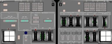
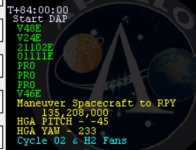
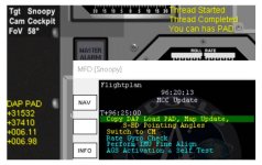
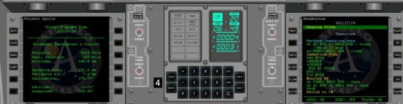
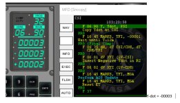
Upon inserting the PAD values for the burn and doing P41 I am in the situation as photo 1 before and at cut off.

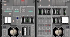
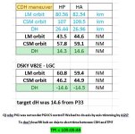
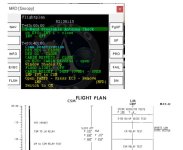
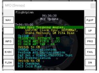
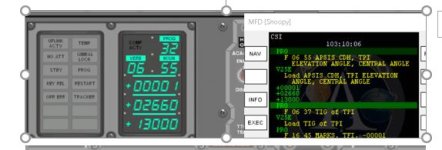
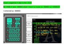
The MFD checklist says “thrust +X” … if I do so I got DVc=0.0 and DVx=0.6 in DSKY, which I brought down to almost 0.0 by trimming resulting in an orbit very close the one predicted by the PAD (see photo 2, N85, V82E and PAD values).

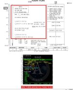
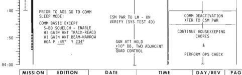
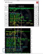
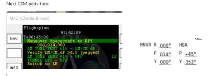
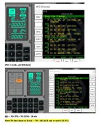
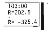
But reading the CSM rendezvous pdf (photo 3) it says to “thrust –X” (AFT) to see the DSKY VGx go from 2.5 to 5.0 -> so it seems I did exactly the opposite, thrusting FWD +X dir going from 2.5 to 0.0 in the DVc.

Where is the catch? Is the P41 checklist “generic” so in this case “I should know to thrust in –X direction (AFT) - Numpad 9” ? (without caring to bring the DVc to 0.0 and later on to trim the values in N85 as "far away from 00000" ) or my burn was correct, as instructed by the MFD checklist (as the resulting HA, HP seems to imply)?

Ah that seems like an oversight to use the generic P41 checklist for that burn, you definitely have to thrust aft, towards -X. We need to fix that in the Checklist MFD. Here have a look in the detailed procedures for all of this: https://history.nasa.gov/afj/ap10fj/pdf/19700026734_mission-f-csm-rendezvous-procedures-19690429.pdf And also for the LM: https://history.nasa.gov/afj/ap10fj/pdf/19700025408_mission-f-lm-rendezvous-procedures-19690428.pdf As you can see there you are supposed to get from 2.5 to 5.0 DV remaining on the DSKY. But check that you are in the right attitude. In P30 you have to enter +0.0 +0.0 -2.5 and the attitude is 0° roll, about 14° pitch, 0° yaw.
 

thermocalc

Active member
Joined
Aug 18, 2014
Messages
217
Reaction score
78
Points
43
Location
Bangkok
Thank you Indy now everything fall into place.
I made some further tests just for trials/learning ... so I got rid of the 525 alarm as you said, trying to be really "face on" to the CSM from the LM and it always worked (no need to uplink again the SVs).
About the AGS causing the gimbal lock ... I realized that somehow when I was seeing the CSM from the left fwd LM window I was "upside down" so to speak, with roll 180 ... and when later on the AGS is in control I saw that he wanted to go to 000 roll, causing the roll and the gimbal lock .... this time i kill rot before (realizing this was the issue) ... so I went back few minutes in the scenario, roll manually to 000, getting again the CSM in the front view and than I engage the AGS and everything worked....
is still a mystery to me understand how I got to roll 180....but i guess it must be when i make the yaw mnvr as i see that when going "through the poles of the FDAI ball" so to speak the roll flips .... .never mind, now i know in which attitude i must be to avoid the gimbal look and i will make sure to be there correctly paying attention to the roll flipping during large yawing.
I skipped the P52 as I was overshooting the DOI burn TIG, but i saved the scenario just for practicing P52 later on tomorrow,, but I did the DOI burn...I thought everything was automatic, like in the CSM, but indeed I saw that i was suppose to manually take over the throttle so i lost time and I end up with a wrong HP ....but I enjoyed the moon landscape in the FWD view while trying more checklists step up to the P30 for the phasing burn....and lunar surface activities.
With better ideas about what to do / expect i will undock again and proceed .... i guess up to the rendezvous I should be able to continue by myself...
I will took the liberty to post some issues I faced so far following the MFD checklist, minor issues, but as you said for P41 maybe there were indeed some "inaccuracies".:salute:
 

thermocalc

Active member
Joined
Aug 18, 2014
Messages
217
Reaction score
78
Points
43
Location
Bangkok
Small “issues” encountered so far in my Apollo 10 mission…I am using NASSP v1822, so as usual if what I am observing is due to my mistakes or outdated version my apologies.

Day 1

1) When performing the “SPS Evasive Maneuver” the automatic checklist execution stop at “DV CG sw – LM/CSM”, the sw is already in LM/CSM but it stops, even flipping up/down doesn’t help.

Day 4

2) I got the “P22 Auto Optics” PADs for LMK IDs: F-1, B-1 and 130; but when the time for observations came (82:15 to 82:50 in A10 FP, and >95h during rev10/11) there were no P22 activities scheduled in the CSM checklist MFD (photo 1); I guess this was “intentionally done” due to parallel activities to be performed in the LM…isn’t it?

3) Around 82:30:00, after the “LM COMM ACTIVATION checklist”, the next CSM task is to change the DAP setting … but before that, the original A10 FP says to MNVR to 135-208-000 and putting the HGA P and Y angles -45 and 234: these numbers were not mentioned -> and this CSM and HGA attitudes are indeed required for making the “S Band Steerable antenna check” at 83h (NOTE: the MFD checklist says to go to 135-208-000 and HGA at -45 and 233 (see photo 2) but at 84h (too late for accomplishing the S band test in the LM at 83h)).

4) Concerning the “S Band Steerable antenna check” itself, it is not mentioned to set the LM antenna to P 148 and Y -4 to carry out the test (photo 3); -> or here are we supposed to know that we should do V64E to read and set the proper angles?

5) moreover, after few time I got a CSM SV update uplink, which is there at 83:15:00 in the A10 FP (photo 3 again) but it was not mentioned in the CSM checklist, so there was no vessel switching to get back to accept the MCC uplink.

6) The call for “Transfer LM to CSM power”, in the groups of LM actions after 84h I think is not temporally correct I think, as it is required while doing the “COMM DEACTIVATION checklist” at 83:40:00 (photo 4), but it appears in the CSM checklist well after 84h (photo 5).
 

Attachments

  • photo 1.JPG
    photo 1.JPG
    48.9 KB · Views: 101
  • photo 2.JPG
    photo 2.JPG
    30.7 KB · Views: 108
  • photo 3.JPG
    photo 3.JPG
    55.9 KB · Views: 112
  • photo 4.JPG
    photo 4.JPG
    43.7 KB · Views: 100
  • photo 5.JPG
    photo 5.JPG
    62.9 KB · Views: 120

thermocalc

Active member
Joined
Aug 18, 2014
Messages
217
Reaction score
78
Points
43
Location
Bangkok
Day 5

7) At 96:25 in the LM (photo 6), after the “RATE GYRO check” there is the “Docked IMU Fine Align”, but the PAD arrive at 96:50 (photo 7); so when we are requested to do V42 we don’t know the angles yet (ok, they can be read by hitting V42 on LGC page of PAMFD so the alignment can be continued) but the PAD arrives later; and looking at photo 7, even after getting the Gyro Angle PAD it is not mentioned to do the “Docked IMU Fine Align”, as instead it is in the A10FP.

8) At about 96:45 you are supposed to enter into 000-014-000 ATT with the CSM, but in the checklist it is not mentioned to put also the HGA to P -45 and Y 353 to be able to re-acquire the signal when the AOS yellow message appears (photo 8) -> or are we supposed to know that we should do V64E to read and set the proper angles? (similar to q4)

9) During the “DAP set, Gimbal Throttle test” the checklist says to enter for Pitch trim and Roll trim +00600, but should not we enter the corrects PAD angles values received earlier (photo 9)?

10) During “Deploy Landing Gear” after flipping the LDG GEAR DEPLOY sw to FIRE, once released to SAFE position the automatic checklist execution stop, need to hit PRO manually to proceed.

11) after undocking the LGC run P47 to null the relative velocities, but it is not written when to exit P47. As the LM should keep station keeping with the CSM until the time of the SEP burn, does it mean that P47 should be terminated when the CSM start preparation for the SEP burn?

12) Before the CSM SEP burn it is written to do V64E to reacquire AOS with the S-band antenna, but it is not mentioned to roll 180 the CSM to 000-015-000.

kind regards.
 

Attachments

  • photo 6.JPG
    photo 6.JPG
    48.7 KB · Views: 98
  • photo 7.JPG
    photo 7.JPG
    47.8 KB · Views: 104
  • photo 8.JPG
    photo 8.JPG
    28.3 KB · Views: 106
  • photo 9.JPG
    photo 9.JPG
    77.4 KB · Views: 115

indy91

Addon Developer
Addon Developer
Joined
Oct 26, 2011
Messages
1,226
Reaction score
588
Points
128
1) When performing the “SPS Evasive Maneuver” the automatic checklist execution stop at “DV CG sw – LM/CSM”, the sw is already in LM/CSM but it stops, even flipping up/down doesn’t help.

I've noticed that before, probably the Checklist MFD doing something wrong, maybe it wants a switch position that doesn't exist or so.

2) I got the “P22 Auto Optics” PADs for LMK IDs: F-1, B-1 and 130; but when the time for observations came (82:15 to 82:50 in A10 FP, and >95h during rev10/11) there were no P22 activities scheduled in the CSM checklist MFD (photo 1); I guess this was “intentionally done” due to parallel activities to be performed in the LM…isn’t it?

Yeah, omitted because of parallel activities.

3) Around 82:30:00, after the “LM COMM ACTIVATION checklist”, the next CSM task is to change the DAP setting … but before that, the original A10 FP says to MNVR to 135-208-000 and putting the HGA P and Y angles -45 and 234: these numbers were not mentioned -> and this CSM and HGA attitudes are indeed required for making the “S Band Steerable antenna check” at 83h (NOTE: the MFD checklist says to go to 135-208-000 and HGA at -45 and 233 (see photo 2) but at 84h (too late for accomplishing the S band test in the LM at 83h)).

4) Concerning the “S Band Steerable antenna check” itself, it is not mentioned to set the LM antenna to P 148 and Y -4 to carry out the test (photo 3); -> or here are we supposed to know that we should do V64E to read and set the proper angles?

5) moreover, after few time I got a CSM SV update uplink, which is there at 83:15:00 in the A10 FP (photo 3 again) but it was not mentioned in the CSM checklist, so there was no vessel switching to get back to accept the MCC uplink.

6) The call for “Transfer LM to CSM power”, in the groups of LM actions after 84h I think is not temporally correct I think, as it is required while doing the “COMM DEACTIVATION checklist” at 83:40:00 (photo 4), but it appears in the CSM checklist well after 84h (photo 5).

Could be more Checklist MFD errors.

Day 5

7) At 96:25 in the LM (photo 6), after the “RATE GYRO check” there is the “Docked IMU Fine Align”, but the PAD arrive at 96:50 (photo 7); so when we are requested to do V42 we don’t know the angles yet (ok, they can be read by hitting V42 on LGC page of PAMFD so the alignment can be continued) but the PAD arrives later; and looking at photo 7, even after getting the Gyro Angle PAD it is not mentioned to do the “Docked IMU Fine Align”, as instead it is in the A10FP.

You will have arrived late in lunar orbit, that is normal for Apollo 10. So all events (DOI etc.) will also happen later than the flight plan. The MCC is also giving PADs etc not on a fixed schedule based on the flight plan but at times relative to crossinging 180° longitude (the definition for the revolution count in lunar orbit). This delay will be 10 to 25 minutes, so it might just be that the PADs you are getting are delayed from the flight plan time by up to 25 minutes.

It could be that the Checklist MFD is missing that V42 step there, we have to check that.

8) At about 96:45 you are supposed to enter into 000-014-000 ATT with the CSM, but in the checklist it is not mentioned to put also the HGA to P -45 and Y 353 to be able to re-acquire the signal when the AOS yellow message appears (photo 8) -> or are we supposed to know that we should do V64E to read and set the proper angles? (similar to q4)

Well now you know to do V64, the checklist seems to require another pass of fixes.

9) During the “DAP set, Gimbal Throttle test” the checklist says to enter for Pitch trim and Roll trim +00600, but should not we enter the corrects PAD angles values received earlier (photo 9)?

Aha, this is a bug. The DAP PAD is calculated for CSM+LM docked, which is wrong, you would want the angles for the LM alone. Currently the shifting center of gravity simulation for the LM is such that it only shifts along the centerline with declining mass. The DAP is a lot happier with that during powered descent. The CG being along the centerline means that the DPS trim gimbal angles are also along the centerline, which means 6° for both pitch and roll is the correct value to enter. For CSM+LM docked the combined center of gravity is taken into account and the CSM already has a variable center of gravity in all axes. So that's how you get angles slightly different from 6°. That needs to be fixed so that the PAD shows LM and CSM weights, but DPS gimbal angles for the LM alone.

10) During “Deploy Landing Gear” after flipping the LDG GEAR DEPLOY sw to FIRE, once released to SAFE position the automatic checklist execution stop, need to hit PRO manually to proceed.

Probably another issue with the checklist file for the Checklist MFD.

11) after undocking the LGC run P47 to null the relative velocities, but it is not written when to exit P47. As the LM should keep station keeping with the CSM until the time of the SEP burn, does it mean that P47 should be terminated when the CSM start preparation for the SEP burn?

Ah the Checklist MFD has directly implemented the descent/phasing procedures document here. It has the PRO to exit P47 which gets you the flasing V37, but doesn't have the 00E required. So you can just do the 00E together with the PRO. Even the actual procedure documents forget to list the full DSKY commands...

12) Before the CSM SEP burn it is written to do V64E to reacquire AOS with the S-band antenna, but it is not mentioned to roll 180 the CSM to 000-015-000.

kind regards.

More Checklist MFD errors it seems.
 

rcflyinghokie

LM Junky
Addon Developer
Joined
Jun 4, 2016
Messages
612
Reaction score
330
Points
78
Location
Colorado
I have been out of town but when I am back I will start a fresh flythrough of 10 and analyze the checklist and correct any errors identified next week.
 

thermocalc

Active member
Joined
Aug 18, 2014
Messages
217
Reaction score
78
Points
43
Location
Bangkok
Hi,
I managed to arrive to the moment when I got the P30 LM INSERTION Pads…before move on with the rendezvous part, I would like ask for some help.

Q1) I saw that P20 was already working in the background when asked to do P30 to load the insertion PAD, but before that I got a 06 49 display with R1 +4 R2 +31… so I just hit PRO and than it blanked again, and I inserted the P30 TIG and DVs (photo 1).
I red elsewhere that the first time marks are taken this display can come up as the SV is not so updated and so I should just hit PRO…I am ok or not up to here, or I have already screwed up my first rendezvous attempt?

Q2) if I have understood correctly, from now on P20 is always working in the background when others programs are called “upon it”, and if everything is right the DSKY should be blank most of the time, and when the COMP ACTY lstays solid on for some time it means it is processing a mark– am I right?

Q3) if after an initial blank screen, a F 50 18 screen appears again, should I hit PRO again to let the automaneuver kicks in? once done and back to F 50 18 again I didn’t realized yet how or which conditions need to be satisfied to get back to a P20 blank screen again. I saw that just by hitting ENTER the F 50 18 stay there, doesn’t blank the display (as it happens at then end for V49E in the CSM for example), but as for q2) is mandatory to have blank screen when running P20 in background?

Q4) when marks are “counting” … if I am running out of time, can I proceed with less marks? Says I should get 15 marks but at count of 12 I am already supposed to do others tasks, can I stop it and move on? Or will I screw up all the rendezvous sequence?

Thanks.
 

Attachments

  • photo 1 P20 running.JPG
    photo 1 P20 running.JPG
    60.7 KB · Views: 111

indy91

Addon Developer
Addon Developer
Joined
Oct 26, 2011
Messages
1,226
Reaction score
588
Points
128
Hi,
I managed to arrive to the moment when I got the P30 LM INSERTION Pads…before move on with the rendezvous part, I would like ask for some help.

Q1) I saw that P20 was already working in the background when asked to do P30 to load the insertion PAD, but before that I got a 06 49 display with R1 +4 R2 +31… so I just hit PRO and than it blanked again, and I inserted the P30 TIG and DVs (photo 1).
I red elsewhere that the first time marks are taken this display can come up as the SV is not so updated and so I should just hit PRO…I am ok or not up to here, or I have already screwed up my first rendezvous attempt?

The mission techniques document has this to say about update limits:

"3.4 LM AND CSM STATE VECTOR CORRECTION LIMITS DURING RDZ NAVIGATION

The LM and CSM differential state vector correction limits (RMAX and VMAX) in the LGC and CSM will be set to 2,000 feet and 2 feet per second. However, the RMAX and VMAX are expected to be exceeded for the first mark after a maneuver or after a long time period of no navigation. Between DOI and CSI, the crew will accept the state vector
corrections if RMAX is less than 12, 000 feet and VMAX is less than 12 feet per second but will verify a downward trend in the magnitude of the corrections as the relative state is continually improved. If the state vector corrections do not decrease, the crew will investigate the tracking data source to verify that the system is operating correctly before
continuing to accept the corrections. If the corrections exceed 12,000 feet or 12 feet per second, the crew will reject the mark and take action to determine if the data source is valid. After CSI, the differential correction acceptability limit will be reduced from 12, 000 feet and 12 feet per second to 5, 000 feet and 5 feet per second since the expected relative errors between the onboard state vector are larger before CSI than following CSI."

Noun 49 shows you nautical miles and not feet, so 12000 ft / 12 ft/s would be

+00197
+00120

and 5000 ft / 5 ft/s would be
+00082
+00050

The internal 2000 ft / 2 ft/s limit that is mentioned is the threshold when it doesn't even show you N49 and just accepts the mark automatically.

Q2) if I have understood correctly, from now on P20 is always working in the background when others programs are called “upon it”, and if everything is right the DSKY should be blank most of the time, and when the COMP ACTY lstays solid on for some time it means it is processing a mark– am I right?

Correct. If you go to P00 or do V56E then P20 will also be stopped, but if you have started P20, DSKY blank and then started one of the P3X programs P20 will run in the background.

Q3) if after an initial blank screen, a F 50 18 screen appears again, should I hit PRO again to let the automaneuver kicks in? once done and back to F 50 18 again I didn’t realized yet how or which conditions need to be satisfied to get back to a P20 blank screen again. I saw that just by hitting ENTER the F 50 18 stay there, doesn’t blank the display (as it happens at then end for V49E in the CSM for example), but as for q2) is mandatory to have blank screen when running P20 in background?

Yes, if you don't have the blank screen then P20 isn't fully running (in the background) yet. Pressing ENTR on the 50 18 doesn't make it go away? Are you in PGNS auto attitude mode? I think normally if you bypass the attitude maneuver it will just drive the RR to the right orientation to track the CSM instead of the LM going to the right attitude. But maybe you are in an attitude where that doesn't work.

Q4) when marks are “counting” … if I am running out of time, can I proceed with less marks? Says I should get 15 marks but at count of 12 I am already supposed to do others tasks, can I stop it and move on? Or will I screw up all the rendezvous sequence?

Yeah 12 marks are totally fine. I'd say even 5 marks, as long as they happened recently and not 30 minutes ago, already means you have a converged solution. As long as you haven't been getting any more 06 49s.
 
Last edited:

thermocalc

Active member
Joined
Aug 18, 2014
Messages
217
Reaction score
78
Points
43
Location
Bangkok
Hi Indy,
thank you.
I now arrive to the moment to run P32 for CSI and I managed somehow P20, RR lock on and Marks...thanks for the valuable inputs (V06 N49 never shown up again so far).
Now I got the CSI PADs with the CSI and TPI TIGs (photo 1).
I run P32, entered the PAD CSI and TPI TIG times and the numbers in the checklist for N55 (photo 3).
than I got 604 alarm (photo 2) ... the G&C dictionary from A11 says TIG TPI - TIG CDH < 10min -> so I recycled V32E by moving the TPI 10 min ahead, new TPI = 105:18:30 (CSI time same as before, N55 values as before) but I got again 604 alarm.
as you can see I am already almost at TIG -15 min ... so i guess I am already too late ?
what should I do now?
thanks.
 

Attachments

  • photo 3.JPG
    photo 3.JPG
    32.1 KB · Views: 110
  • photo 2 604 alarm.JPG
    photo 2 604 alarm.JPG
    69 KB · Views: 142
  • photo 1 CSI PAD.JPG
    photo 1 CSI PAD.JPG
    62.7 KB · Views: 125

indy91

Addon Developer
Addon Developer
Joined
Oct 26, 2011
Messages
1,226
Reaction score
588
Points
128
Moving the TPI time would be a last resort, something seems to have gone quite wrong. Can you give me the scenario before or when the program alarm has just happened? 604 alarms really shouldn't happen, there should be plenty of time between CDH and TPI. CDH usually happens an hour after CSI, so according to the PAD there would be 38 minutes between CDH and TPI. Maybe you just entered the TPI time wrong in N37? That would be the easiest explanation.
 

thermocalc

Active member
Joined
Aug 18, 2014
Messages
217
Reaction score
78
Points
43
Location
Bangkok
thank you for helping .... in the zp the scenario with the alarm 604 is the one when I put the TPI time at 105:18:30 (10 min later; sorry the 1st time I got 604 i didn't save it);
the other is when I need to start P32 ... the PAD are available by "5" in the MCC menu....
but, GENRALLY speaking, is it correct to input as INITIAL trial solution the CSI and TPI TIG from the PAD?
as far as I have understood the final TIG and DVs for CSI will come by running P32 few times .... right?
 

Attachments

  • P32-and-alarm-604.zip
    136.2 KB · Views: 110

indy91

Addon Developer
Addon Developer
Joined
Oct 26, 2011
Messages
1,226
Reaction score
588
Points
128
Ok I tried the earlier scenario where you are just entering P32 and everything worked fine. I checked the later scenario where you already have the program alarm and the TPI time (Noun 37) is actually all zeros. So it must have been an error with entering that time.

With P20 and P32 running at the same time the AGC is quite busy. So when entering data like N37 it can happen that after the ENTR the AGC will have the COMP ACTY light on for a bit. You must have proceeded to the next display before the AGC really registered that you had entered anything into the DSKY, or something like that. I would just try again from that first scenario and make sure that you don't try entering any data or press PRO while the COMP ACTY light is permanently on.
 

thermocalc

Active member
Joined
Aug 18, 2014
Messages
217
Reaction score
78
Points
43
Location
Bangkok
thank you very much ... ok i will do as you suggested, and happy to see it was just a silly error, thank for your time, and the doc in the link you provided it is really nice, just started reading and already found some answers, tomorrow at office i will print it out and study before to proceed further. Have a good day...my is almost over :salute:
 

thermocalc

Active member
Joined
Aug 18, 2014
Messages
217
Reaction score
78
Points
43
Location
Bangkok
Hi, managed to get P32 working and I did the CSI burn and now proceeding for P33 and CDH burn;
but I guess I did something stupid again so please allow me to ask for clarity.

Q1) about V90 “Out of plane display” – I called V90E (in the LM computer) and read out the Y-dot velocity, in my case after entering the CSI TIG time it was -00003 for Y-dot (-0.3 fps) – photo 1

Next when asked to “Insert Negative Ydot in R2” during F 06 81 what should I enter?

The OPPOSITE of what I read out? So as I read -00003 should I enter +00003? Or just “-00003” which is already negative?
I entered the SAME VALUES, -00003 (photo 2), so I have the feeling to be wrong ....but I don’t fully understand what V90 does: is showing the velocity perpendicular to the LM orbital plane to match the CSM orbital plane? If so why should I change the sign? OR , as I have seen in some checklists, the CSM was supposed to run V90 and “voice” the value to the LM? This could explain why a change of sign is required, what should I have entered? I was right or wrong - between photo 1 and 2?

Q2) upon doing all LM burns when asked to trim the residuals…I saw that getting 0.0 fps is quite difficult, I end up with mostly +/- 0.1 or +/- 0.2 fps at best … are these values “acceptable” in order to succeed in the rest of rendezvous or must they really brought down to 0.0 in all axis? If so any “tricks” to make this happen? Like x0.1 or staff like that?

Q3) still out of curiosity, I was wondering how the CMP can know the range rate of the LM during the rendezvous profile? Range he gest from the VHF ranging, but R-rate? (see photo 3).
NOTE: I tried V83E in the CSM; but in R1 and R2 I got “numbers” which are not looking any closer to the ones in the square boxes, or even R1 is not at all near the RANGE values I got in the EMS…is this because V83E R and R-rate information are only “reliable” when in closed proximity, such as during coast from TPI to TPF?

Thanks.
 

Attachments

  • photo 1.JPG
    photo 1.JPG
    87.1 KB · Views: 112
  • photo 2.JPG
    photo 2.JPG
    84.5 KB · Views: 106
  • photo 3.JPG
    photo 3.JPG
    11 KB · Views: 105

indy91

Addon Developer
Addon Developer
Joined
Oct 26, 2011
Messages
1,226
Reaction score
588
Points
128
Q1) about V90 “Out of plane display” – I called V90E (in the LM computer) and read out the Y-dot velocity, in my case after entering the CSI TIG time it was -00003 for Y-dot (-0.3 fps) – photo 1

Next when asked to “Insert Negative Ydot in R2” during F 06 81 what should I enter?

The OPPOSITE of what I read out? So as I read -00003 should I enter +00003? Or just “-00003” which is already negative?
I entered the SAME VALUES, -00003 (photo 2), so I have the feeling to be wrong ....but I don’t fully understand what V90 does: is showing the velocity perpendicular to the LM orbital plane to match the CSM orbital plane? If so why should I change the sign? OR , as I have seen in some checklists, the CSM was supposed to run V90 and “voice” the value to the LM? This could explain why a change of sign is required, what should I have entered? I was right or wrong - between photo 1 and 2?

R2 in V90 (the Ydot) is your out-of-plane velocity relative to your target. What you are trying to do is get the out-of-plane movement as small as possible without having to perform a dedicated plane change maneuver. That's why you use the CSI time and then load as DVY in N81 the negative (sign reversed) of the YDOT, which accomplishes that the YDOT relative to your target is being nulled. You can imagine your movement out-of-plane relative to the target like a sine wave. The CSI maneuver will be anywhere on that curve and by applying the negative YDOT the point at which CSI happens is now the new peak of the sine wave. If you are really lucky then CSI happens exactly at the point where you are crossing the orbital plane of the target (Y=0, YDOT= some value). Then the CSI maneuver with negative YDOT will make you completely in-plane with the target. But where on that sine curve you currently are is of course mostly random.

It gets even more confusing when you compare the YDOT with the value from V90 done in the other vehicle. Because for the other vehicle the definition of the sign of YDOT is reversed, as it's the out-of-plane velocity of the CSM and not LM. So if you in the LM would want to use the YDOT from V90 done in the CMC then you would have to use the negative of the negative...

Q2) upon doing all LM burns when asked to trim the residuals…I saw that getting 0.0 fps is quite difficult, I end up with mostly +/- 0.1 or +/- 0.2 fps at best … are these values “acceptable” in order to succeed in the rest of rendezvous or must they really brought down to 0.0 in all axis? If so any “tricks” to make this happen? Like x0.1 or staff like that?

Yeah, 0.1/0.2 is pretty good. I'd say below 0.5 in each axis is already acceptable.

Q3) still out of curiosity, I was wondering how the CMP can know the range rate of the LM during the rendezvous profile? Range he gest from the VHF ranging, but R-rate? (see photo 3).
NOTE: I tried V83E in the CSM; but in R1 and R2 I got “numbers” which are not looking any closer to the ones in the square boxes, or even R1 is not at all near the RANGE values I got in the EMS…is this because V83E R and R-rate information are only “reliable” when in closed proximity, such as during coast from TPI to TPF?

The CMP would know the range rate with V83, yes. Is your CMC even updated with the latest LM state vector? Did you uplink a new one or did you perform a lot of P20 with sextant and/or VHF ranging? Because P76 is probably not going to be accurate enough with multiple LM maneuvers. Provided the state vectors are up-to-date V83 range and range rate should be quite accurate. The calculations kind of break down below 1NM range, so it is at small ranges where V83 is actually inaccurate.
 

thermocalc

Active member
Joined
Aug 18, 2014
Messages
217
Reaction score
78
Points
43
Location
Bangkok
thanks Indy.
q1) so I did indeed wrong .... if I read -0.3 fps doing V90 in the LM I should have entered +0.3 in N81 ....
q3) AHHHHHHHHHH...forgot the SVs as of cousre all CSM activities were not done ... I will just try once to uplinks the SVs via RTCC and call up V83E and check ...
:coffee::coffee::coffee:still reading your pdf rendezvous doc before to proceed...very nice, as it explains also A11 .... (y)
 

thermocalc

Active member
Joined
Aug 18, 2014
Messages
217
Reaction score
78
Points
43
Location
Bangkok
Sorry I am still back with some new issues…

1) With reference to photo 1 taken at the end of the CSI burn, at approx. 103:40:00, I noticed that I got a red flag on top of the THRUST indicator; and it there also when I did the CDH burn, at approx. 104:40:00, see photo 2. Is normal at this time in the mission?

2) I also noticed that the RCS A and B temperature are very low, bottom scale in the gauge, and the RCS quantity is almost empty…after CDH (photo 2) it is almost zero….so I guess I used too much RCS propellant? Something went wrong when I was supposed to do the Ascent Stage propellants interconnect procedure? (I think, that at that time I let the automatic checklist execution ON – to gain time - and maybe some spring loaded switches were not actuated? So that unwittingly I kept draining RCS fuel/oxidizer all times?)

3) When I did the CDH burn (photo 2), as soon as I hit the translational jets I got a RCS TCA C/W alarm as well as all red flags labels on system B …see photo 2. As the propellant quantity was almost zero in system B does it mean I run out of fuel? And so got the alarms and red flags?

4) When I did the CDH burn I used P41, but I saw that I was not supposed to let F 50 18 kicks in to put the LM in the proper burn attitude….instead I was supposed to pass control to the AGS. Anyway, I did F 50 18 and I thrusted only along the X direction (before that I saw I had to null all three components of velocity on the DSKY) … so I have the feeling that I was wrong again, should I had to do the “AGS axis by axis trimming procedure?”, but i guess I end up in a good orbit at least (photo 3).

Thank you for your patient to guide me through my first rendezvous attempt :cry:
 

Attachments

  • photo 1.JPG
    photo 1.JPG
    82 KB · Views: 106
  • photo 2 RCS TCA Alarm and red flags.JPG
    photo 2 RCS TCA Alarm and red flags.JPG
    124.4 KB · Views: 109
  • photo 3.JPG
    photo 3.JPG
    69.3 KB · Views: 102

rcflyinghokie

LM Junky
Addon Developer
Joined
Jun 4, 2016
Messages
612
Reaction score
330
Points
78
Location
Colorado
1) With reference to photo 1 taken at the end of the CSI burn, at approx. 103:40:00, I noticed that I got a red flag on top of the THRUST indicator; and it there also when I did the CDH burn, at approx. 104:40:00, see photo 2. Is normal at this time in the mission?

2) I also noticed that the RCS A and B temperature are very low, bottom scale in the gauge, and the RCS quantity is almost empty…after CDH (photo 2) it is almost zero….so I guess I used too much RCS propellant? Something went wrong when I was supposed to do the Ascent Stage propellants interconnect procedure? (I think, that at that time I let the automatic checklist execution ON – to gain time - and maybe some spring loaded switches were not actuated? So that unwittingly I kept draining RCS fuel/oxidizer all times?)

3) When I did the CDH burn (photo 2), as soon as I hit the translational jets I got a RCS TCA C/W alarm as well as all red flags labels on system B …see photo 2. As the propellant quantity was almost zero in system B does it mean I run out of fuel? And so got the alarms and red flags?
Yep you ran out of RCS propellant it appears. Your temperature displays are controlled by the TEMP/PRESS MON knob you might not have it selected.

The TCA alarms are being triggered because its commanding a jet to fire but not detecting any chamber pressure because of lack of propellant. How much RCS did you have before liftoff? After liftoff?
 

thermocalc

Active member
Joined
Aug 18, 2014
Messages
217
Reaction score
78
Points
43
Location
Bangkok
ahahahah...as simple as that....run out of propellant ... ok so need to be more conscious about them....i will try to improve.
i started from undocking with full tanks so i guess i was not careful enough....never mind, I will re-do all over again practice will help to sort it out.
thanks
 

indy91

Addon Developer
Addon Developer
Joined
Oct 26, 2011
Messages
1,226
Reaction score
588
Points
128
4) When I did the CDH burn I used P41, but I saw that I was not supposed to let F 50 18 kicks in to put the LM in the proper burn attitude….instead I was supposed to pass control to the AGS. Anyway, I did F 50 18 and I thrusted only along the X direction (before that I saw I had to null all three components of velocity on the DSKY) … so I have the feeling that I was wrong again, should I had to do the “AGS axis by axis trimming procedure?”, but i guess I end up in a good orbit at least (photo 3).

The CDH maneuver is nominally 0 ft/s. And even the actual CDH maneuver won't be very large, a few ft/s at most, but in some random direction (mostly radial). So the normal technique for it is basically like residual nulling and not like a longer maneuver like CSI. That's why you wouldn't normally perform an attitude maneuver to make it a X-axis only burn, you don't gain anything from that.
 
Top