Apollo 10 with NASSP 8 beta rev 1822_issues

thermocalc

Active member
Joined
Aug 18, 2014
Messages
217
Reaction score
78
Points
43
Location
Bangkok
Hi to everybody.
I just started (few days ago) Apollo 10 mission and I was hoping to get close to the Moon before asking questions but apparently I was wrong :cry:
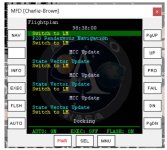
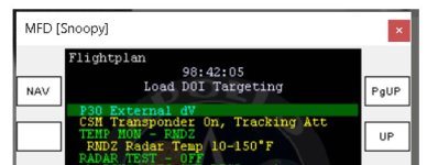
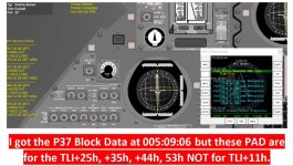
I arrived to the point to extract the LM from the LV and get into the SPS Evasive mnvr attitude by V49E ... (the P30 PAD I received can be seen by the MCC menu hitting 5)
---please forget the fact that I am behind the timeline, I can re-do sep/dicking later on to improve, this was just my first attempt of A10 ...

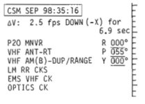
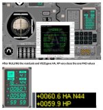
anyway I was supposed to enter for the R-P-Y angles these values V25E +00100E +25500E +35800E
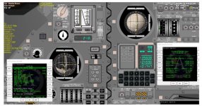
and when I got F 06 22 nothing happen and I get back to F 05 18 ... the DAP doesn't rotate the CSM/LM stack
I checked V48E and I have 21102 and 01111 and after PRO PRO I made again V46E to make sure it was activated; and V62E to get the error needles...than did again V49E and still no jet firing.
(manually I can move to the burn attitude, so manually the RCS jets seems to work)

don't understand why the DAP doesn't work at this point in the checklist ... I guess / think to have followed all steps as didn't have any issues to separate and docking earlier on.

(NOTE: I docked manually, i didn't use V49E to reach the docking attitude ... so this is the first time in the mission when I am using the automaneuver)

could you please have a look to my file and see if I missed some CBs or SWs ??? or maybe you already fugured out by what I have done why the DAP doesn't work?
thanks.
 

Attachments

  • T_+4h_12m_SPS_Evasive_Attitude.zip
    55.2 KB · Views: 117

thermocalc

Active member
Joined
Aug 18, 2014
Messages
217
Reaction score
78
Points
43
Location
Bangkok
SORRY for the false alarm --- my fault:
after drinking a coffee :coffee: 
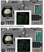
and ri-checked saved scenarios I saw/realize that the "THC was on CW position" -> putting on neutral position solved the problems ->ashamed of me not seeing it before posting-and don't know why I put it there ... in a scenario before that it was neutral ... i guess I hit by mistake during panel scrolling or something like that...
I am now at about 5h 30m starting P23 ... bye & sorry for the useless post (I guess I cannot remove it by myself or in case I don't know how to do it).
Fill free to remove it if you can do it, to avoid false alarms.
 

n72.75

Move slow and try not to break too much.
Orbiter Contributor
Addon Developer
Tutorial Publisher
Donator
Joined
Mar 21, 2008
Messages
2,687
Reaction score
1,337
Points
128
Location
Saco, ME
Website
mwhume.space
Preferred Pronouns
he/him
No worries. This is more common than you might think. The solution is always more coffee.
 

thermocalc

Active member
Joined
Aug 18, 2014
Messages
217
Reaction score
78
Points
43
Location
Bangkok
:cheers:
finished for day 1, put the crew to sleep and I will also go soon...
but I would like to report a strange situation with the automatic MCC messages.
I got the P37 TLI+4h abort PAD on time, and when I was supposed to get the P37 TLI+11h abort PAD I got instead the PADs for the TLI+25h, 35h, 44h, 53h;
finally when I was supposed to get the TLI +25h, 35h, 44h, 53h PAD I got again the same PAD (as received earlier instead of the TLI+11h).
see photo and GET (sim time) when I got them.
In my previous A11 all abort PADs were ok, and also here in A10 day 1 all others MCC PADs came more or less on time (SOS Evasive, MCC1, PTC refsmmat).
just a glitch?:unsure:

next I would like to ask for a confirmation, as even if it is a matter of few seconds it still confuse me:
WHAT IS THE TLI TIME? Used to generate the automatic MCC messages/events....

TB6+9'38'' IS THE TLI-START
+BURN TIME GIVE ME THE TLI-CUT OFF -> IS THIS THE TLI TIME? -> in my case was 2:39:02
OR NEED TO ADD THE +10 SEC OF TAIL OFF , TO GET THE TLI TIME?t -> in my case was 2:39:12
OR IT THE GET TIME WHEN I GET THE "TLI TREATH" MESSAGE -> in my case around 2:39:22 (see photo TLI)

I asked because sometime I saw things happening as if the TLI was assumed to be 2:39:02, but for the MCC automatic PADs seems to be few seconds later ... or is it just normal some sort of delay ....

of course nothing to worry but having flown A8, A11 and now A10 I do realize something is not fully clear about the TLI sequence...

thanks.
 

Attachments

  • P37 Abort PADs day 1.JPG
    P37 Abort PADs day 1.JPG
    112.1 KB · Views: 139
  • TLI time what is it correctly.JPG
    TLI time what is it correctly.JPG
    127.2 KB · Views: 145
  • TLI plus 11h P37 abort PAD not received.JPG
    TLI plus 11h P37 abort PAD not received.JPG
    133.2 KB · Views: 134

indy91

Addon Developer
Addon Developer
Joined
Oct 26, 2011
Messages
1,224
Reaction score
582
Points
128
Well in general the Translunar Injection is the whole process. The TLI message from the MCC comes up 18 seconds after the predicted time of TLI cutoff (end of thrust tailoff). Not sure why I chose 18 seconds there really, maybe to give it a few more seconds time if things don't go exactly as predicted. The MCC logic checks in what timebase the LVDC is (5 = Earth orbit, 6 = TLI prep through TLI cutoff and 7 = after TLI cutoff) at that time, because it has the ability to calculate a TLI PAD for the second TLI opportunity. If at TLI cutoff plus 18 seconds it is still or back in timebase 5 then the MCC would calculate a second TLI PAD a bit later. Otherwise it will go to the translunar calculations.

The ignition times for the translunar abort maneuvers... I had looked at the actual times and had trouble figuring out a pattern really. What I ended up doing was this:

double TLIbase = floor((calcParams.TLI / 1800.0) + 0.5)*1800.0; //Round to next half hour

So the time of TLI cutoff rounded up to the next half hour and the e.g. 11 hours added for TLI+11. How they came up with those times seems somewhat random across the missions, seems like each RETRO flight controller just did it as he liked. I just tried to find a pattern for each mission looking at the actual ignition times they used.

And for the P37 PADs, that is a bug. Basically the first P37 PAD was calculation number 5 (TLI+11/25/35) and the second one was number 6 (TLI+25/35/44/53). But then I had added in some more calculations and they became number 8 and 9. But what I failed to change was the logic that decides which of the two calculations is happening, right now it is still checking if the calculation number is 5, in code
Code:
if (fcn == 5)
But of course that now is never the case (it's only ever 8 or 9), so that logic in both cases decides to calculate the TLI+25/35/44/52 PAD. I'll get this fixed very soon, easy to do and luckily not a bug that prevents you from continuing the mission!
 

thermocalc

Active member
Joined
Aug 18, 2014
Messages
217
Reaction score
78
Points
43
Location
Bangkok
thanks Indy, maybe now the timing start making more sense: as I said the TLI MCC message came up at 2:39:22, if I remove the 18s it gives me 2:39:04 .... and now with more MCC messages received (just got the PAD for MCC-2 run) it seems to me that they always come at xx:xx:04 sec -> which is consistent with your 18 sec .... I was confused as cut off was at 2:39:02 and tail off 10s later ... so i was not getting from where the "04" second "look-like pattern" was coming about .... thanks, something more clear...learning by doing as usual and asking if in doubt :salute: ---
 

thermocalc

Active member
Joined
Aug 18, 2014
Messages
217
Reaction score
78
Points
43
Location
Bangkok
Hi, just arrived safely into lunar parking orbit…around GET 76:00:00.

But I am not happy, so before go on I would like to ask you something.

After TLI I did only the MCC-2 and I didn’t trim the velocities (as in the FP) even if I end up with -0.5 fps in the DVc (N85 gave me -0.3, 0.0, +0.2 fps);
than MCC-3 and MCC-4 were scrubbed and after LOI-1, without trimming (as in the FP), I end up into a lunar orbit of 167.0 x 50.7 nm (on PAMFD) and 168.7 x 52.3 nm (doing V82E).
Theoretically I was supposed to arrive at 170 x 60 nm -> I think I am far too low...

(with A11, still without trimming and doing only MCC-2 and LOI-1, I ended up with 167.1 x 58.6 nm (in PAMFD) and 169.1 x 60.2 nm (doing V82E))-> which sounded more reasonable to me.

The question is:
if well before MCC-3 (and maybe MCC-4) my trajectory was putting me well below HP=60, why I didn’t got the PADs for making the corrections?
If this was due to “too small DV”, than with my trajectory being off a bit, why the LOI-1 burn itself didn't try to correct my trajectory burning in some other angles to raise a bit the perilune?

To avoid these situations, should I "trim" in anycase after cut-off if the residuals are higher than 0.1-0.2 fps says?

Is this orbit, in which I am now, suitable to carry out the rest of the mission and rendezvous?
Or better if I try all over again, or just start from the LOI-1 scenery in the default folder? (not sure if it can work without issues in the new rev.1822…)

Thanks.
 

indy91

Addon Developer
Addon Developer
Joined
Oct 26, 2011
Messages
1,224
Reaction score
582
Points
128
The orbit should be fine, it intersects 60NM altitude so the logic for calculating LOI-2 should be able to get you into a circular 60NM orbit, even if the DV will be a bit larger than usual. Shouldn't be a problem continuing.

For the issue, I would like to look at a scenario before the MCC-3 calculation. The decision logic for how and if to perform MCC-3 and 4 is fairly complicated, so I can't easily tell you what went wrong. But I think something definitely did go wrong.

If the flight plan says don't trim then not trimming residuals is fine. I think it's the MCC targeting being at fault here.
 

thermocalc

Active member
Joined
Aug 18, 2014
Messages
217
Reaction score
78
Points
43
Location
Bangkok
dear Indy, thank you for your time.
In the zip file some scenario files, photos of PAD I got (you should get the same running the scenaries) and my LOI-1 BURN status (in the doc file)

i gave you the following scenarios:

at 52h waiting for MCC-3 decision -> I got the MCC-3 scrubbed message at 52:16:50
at 69h waiting for MCC-4 decision -> I got the MCC-4 scrubbed message at 69:16:50
at 71h waiting for LOPI-1 preliminary PAD -> I got it at 71:16:50 (see here that the HP is already <60 in the PAMFD but the predicted orbit in the PAD is 170x52.4)
at 74h waiting for LOPI-1 final PAD -> I got it at 74:16:50 (see here that the HP is almost 50 nm in the PAMFD but the predicted orbit in the PAD is still 170x52.4)

I gave you also two others just before TIG - 30sec and one a bit earlier during the SXT STAR check (if you can check my alignment was correct and Landing Site REFSMMAT).

goodnight :sleep: (day over for me...)
 

Attachments

  • For-Indy_LOI-low-orbit-issue.zip
    2.9 MB · Views: 126

indy91

Addon Developer
Addon Developer
Joined
Oct 26, 2011
Messages
1,224
Reaction score
582
Points
128
Ah that's a whole package, I'm sure I can figure it out with that, thank you!

EDIT: Preliminary analysis: Everything is actually fine, kind of!

The MCC targeting is mostly following the Apollo 10 mission rules, specifically rule 5-60:

LOI SHALL BE TARGETED WITHIN THESE CONSTRAINTS :

A. 60 > hp >50 (LUNAR PARKING ORBIT).
B. THE PERICYNTHION OF THE APPROACH HYPERBOLA WILL BE MAINTAINED WITHIN 50 AND 70 NM.
C. THE ALTITUDE OF THE NODE (BETWEEN THE APPROACH HYPERBOLA AND THE DESIRED LPO) WILL BE MAINTAINED BETWEEN 50 AND 75 NM.

In your case the pericynthion altitude is 51.4 NM. The altitude of the node (basically the altitude of the point in space where LOI-1 would happen if it was an instantaneous maneuver, ideally it would be the same as pericynthion) is 52.5 NM. So neither of these really violate the 50 NM constraint. But because that instant LOI-1 maneuver has to happen at 52.5 NM the LOI-1 targeting has no choice to adjust the orbit after LOI-1 to 52.5 x 170 instead of 60 x 170. What you really want of course is 60 NM circular after LOI-2 and as long as the perilune is below 60 NM that can always be done.

I'm not even really finding a disagreement with the mission techniques document. It has some additional constraints in the MCC-3/4 decision logic, but I don't see any of them violated in your trajectory. Now I have to think about this for a while, if I am missing something and if I actually want to make the MCC logic stricter so that it does MCC-4 despite those guidelines.
 
Last edited:

thermocalc

Active member
Joined
Aug 18, 2014
Messages
217
Reaction score
78
Points
43
Location
Bangkok
just woke up and check quickly the forum...thank you as usual...happy to see that I didn't do anything wrong so far, and happy to see that even according the mission rules this situation might be happened also in reality, i just try to skip forward in time (bypassing all checklist and FP activities) to the LOI-2 PAD and indeed it seems that the PAD will put me into a nice circular orbit 60:0 x 60.2 ... i didn't execute the burn yet....i was just curious ... tonight after work i will try from 76h following all steps....i will enjoy the view of the lunar surface at lower distance for a while :) ....eheheh. Bye
 

thermocalc

Active member
Joined
Aug 18, 2014
Messages
217
Reaction score
78
Points
43
Location
Bangkok
Hi Indy, sorry to bother you again .. I tried all steps from 76h to 78h 30m ... I got the LOI-2 PAD at about 78:27:13 (the same I got this morning) and this time I did the uplink ... but the uplink stop and I got an OPR lt on ... as the CMC was "stacked" I just did V37E 00E ... I tried P30 but there were not target load updated, the new LOI-2 TIG was not uploaded ... I also try to check with V82E of the HO/HA from the CMC were more or less equals to the ones in the PAMFD but they were off few nm (usually after the CSM SV upload they are always within 0.X error from each others).....don't know why I got the OPR.....scenery in attached file, from 78h just time skip ahead...
thanks in advance.
 

Attachments

  • T-78h.zip
    56.3 KB · Views: 125

rcflyinghokie

LM Junky
Addon Developer
Joined
Jun 4, 2016
Messages
608
Reaction score
327
Points
78
Location
Colorado
Uplink worked fine for me, I wonder if you pressed a DSKY keyboard command by accident or didnt let it go to P00 before the uplink. Is the OPR ERR reproducible for you?
 

thermocalc

Active member
Joined
Aug 18, 2014
Messages
217
Reaction score
78
Points
43
Location
Bangkok
dear RCFLY, thanks for checking, and sorry for the delay, but I could not run the sim before due to real life problems .
I don't know why I got the OPR lt on, but indeed I tried 2 - 3 times to run the same scenario I posted earlier and no problems, so it worked also for me, don't know what I did wrong few times back then before posting...maybe I guess I was just too tired and I hit some keys by mistake...
So now I am happily in a 60.5 x 59.8 NM orbit at the time to enter the LM the first time and starting all the P22's ... so the LOI-2 targeting worked as a charm as Indy explained, despite my bad arriving orbit it got corrected into a near perfect circle .... the LOI-2 PAD gave me 60.6 x 60.0 so at the end I was not far off.
Now the harder part start....the LM...my weakest point.....so stay tuned for further questions....thanks a lot so far. Bye
 

thermocalc

Active member
Joined
Aug 18, 2014
Messages
217
Reaction score
78
Points
43
Location
Bangkok
Hi to all,

I slowly arrived to the AGS CALIBRATION and CSM-LM UNDOCKING steps (around 98h) but I have a bit of confusions accumulated so far with the CSM ATTITUDES, and later on (after undocking) with the LM ATTITUDES, so better I ask to clear all doubts.

Q1) Looking at the CSM ATT before the AGS Calibration test in the A10 original FP (photo 1), when it says: “MNVR UNDOCK ATT R=180, P=015, Y=014 (EXCEPT YAW)”, and further down “YAW LEFT 014° AFTER AGS CALIBRATION” ....I understood that I must be at 180-015-014 for the AGS CAL Attitude, and at 180-015-000 for the UNDOCKING ATTITUDE. Am I correct?

Q2) “Yaw LT” = NumPad 1 & “Yaw RT” = NumPad 3 -> according Orbiter ROT controller ... isn't it?

But does YAW “RT” and YAW “LT” depends also on the roll angle? I ask, because it is not clear the meaning of the “Yaw left 014° instruction…” -> as if I am at 180-015-014 and I yaw left (Numpad 1) by 14° at the end of the AGS Calibration I end up to Y=028, to go to Y=000 I need to use “Numpad 3=, i.e. “Yaw RT”. Looks like that being “upside down” at R=180 the “left/right” are “reversed” -> is it “REVERSE SENSING”? -> so that if the FP says to “yaw LEFT”, being at R=180 astronauts should know/realize that in reality they have to “yaw RIGHT”? (indeed if I am at 000-015-014 doing a yaw left by 14° I go to 000-015-000) -> so the confusions when trying to follow "literally" the instructions.


Q3) similarly, once inside the LM immediately after undocking the FP says to YAW RT 120° and than PITCH UP 90° to see the CSM through the FWD WDW…so If I do a 120° yaw RT rotation (Numpad 3) from the undocking attitude followed by a pitch up (Numpad 2) 90° rotation I can see the CSM (see photo 2 and sequence of rotations).

BUT I can see it also If I do the reverse, namely a 120° yaw LF rotation (Numpad 1) followed by a a pitch up 90° rotation (Numpad 2), but the imagine I get is somehow a “mirror one” (see photo 2 and sequence of rotations).
So according the FP instructions, I was doing correctly the rotations as in photo 2 or 3?

Thanks for the clarifications.
 

Attachments

  • photo 3 LM yaw LFT 120 and Pitch UP 90 sequence.JPG
    photo 3 LM yaw LFT 120 and Pitch UP 90 sequence.JPG
    108.6 KB · Views: 125
  • photo 2 LM yaw RT 120 and Pitch UP 90 sequence.JPG
    photo 2 LM yaw RT 120 and Pitch UP 90 sequence.JPG
    118 KB · Views: 136
  • photo 1.JPG
    photo 1.JPG
    14.9 KB · Views: 126

thermocalc

Active member
Joined
Aug 18, 2014
Messages
217
Reaction score
78
Points
43
Location
Bangkok
Hi, I found the document " CSM rendezvous procedure - F Mission" and I saw that the UNDOCKING attitude was indeed 180-014-000, so everything makes more sense now, this for my Q1.

For the others queries, I played a bit with the LM Attitude modes and I realized that I was wrong in reading out the Yaw angles from the LM FDAI .... so indeed I didn't rotate by 120 in yaw that's why I got all those weird attitudes....and now with the proper angles (read out) all make sense.
let's carry on now .... thanks.
(y)
 

rcflyinghokie

LM Junky
Addon Developer
Joined
Jun 4, 2016
Messages
608
Reaction score
327
Points
78
Location
Colorado
Hi, I found the document " CSM rendezvous procedure - F Mission" and I saw that the UNDOCKING attitude was indeed 180-014-000, so everything makes more sense now, this for my Q1.

For the others queries, I played a bit with the LM Attitude modes and I realized that I was wrong in reading out the Yaw angles from the LM FDAI .... so indeed I didn't rotate by 120 in yaw that's why I got all those weird attitudes....and now with the proper angles (read out) all make sense.
let's carry on now .... thanks.
(y)
Sorry I missed this! I am glad you were able to sort them out :)
 

thermocalc

Active member
Joined
Aug 18, 2014
Messages
217
Reaction score
78
Points
43
Location
Bangkok
Hi, thanks to reply, no problems I am very slow to carried out the mission, as too many real life issues who makes me feel very tired in the evening and hard to concentrate...can use only the weekends to really move on few hours into the missions :cry: :cry: wish all of you guys and NASSP were "out there" 20 or 30 years ago when I was a free man with a lot of free time....:cool:

I have undocked finally but I am now facing some issues as follows.

q1) when the CSM does the separation burn do I need to inform the LGC of that by doing P76 into the LM? the MFD checklist doesn’t say that; but after the burn I got a CSM SV update MCC message, so I guess this was “mimicking” the P76 done by the crew? Or do we need still to do P76 by ourselves?

q2) similarly, when the LM does the DOI burn, and later on the PHASING burn, shall I need to do P76 in the CMC? Or there will be MCC updates? Is the meaning of all the occurrences of MCC SV updates in the CSM MFD checklist done to mimic these P76s? (see photo 1)

q3) generally speaking about the CSM activities performed after undocking: due to heavy workload inside the LM (RR tests, P52, and so on) are we “expected” to carry on also all CSM activities done by the CMP at the same time (as appearing in the A10 FP left column?), like taking marks or reading range and range rate, flipping communication switches and so on …. or can we “safely” neglect them in order to rendezvous? concentrating only on the LM?

q4) after the P30 done in the LM to enter the DOI target loads, when I need to make the RR and VHF range check the CSM checklist doesn’t say to set the communications sws/knobs inside the CSM to make the VHF RANGE system working, but later on it says to check for R and R-rate comparison between RR and CSM VHF (while for the LM it does say how to set the switches); eventually I got it working (thanks to your and Indy reply on the VHF RANGE set-up in another post) but I would like to know if this missing information was intentionally done or not?

Q5) also around this time, see photo 2 the yellow text says “CSM transponder on, Tracking Attitude” – which I guess it is 000-055-000 (by photo 3) -> before this moment I was still in 000-015-000, and after that it says to do P20 --- so do I need to be in 000-055-000 BEFORE to call up P20?

Q6) when I do P20 in the CSM shall I need to keep it running all times? even when the LM does the DOI and PHASING burns? it is only written “exit when observation end” but when it is supposed to end? If I don’t do anything I saw the LM is kept into the FOV of the SCT …. So shall I need to let it like this while going back into the LM, doing all other tasks (RR check, P52, DOI,…)?

q7) when inside the LM it is time to do the RR test I got the following weird effects: the first time I called P20 it didn’t show any auto maneuver (no F 50 18) but it greeted me with F 50 25 00201, I carried on hitting ENTER and slew the RR antenna manually to get lock on; but according the checklist I should have seen F 50 18 with the new FDAI angles (I guess to “face” the CSM) and maneuver to do so, but it didn’t happen; is this because I was already facing the LM?

q8) connected to q7) above, initially I was not able to get any signal and it took me some time to figure out that I had the RR still at 000-283 angles, and when I slew it to 000-000 (looking the angles in V16 N72E) it worked; question is, how do I know where is the RR antenna without looking "outside" or to the angles themselves in N72?? I think to remember that the P-Y error needles in the FDAI were centered but the I was not at 000-000, only later on when they were 000-000 in N72E the needles were centered into the FDAI...so the confusion...

q9) once managed to get lock on in LGC at some time I got a 00525 alarm….I understood that something is wrong with the lock-on (main lobe or side lobe story read elsewhere) or the state vectors knowledge of the CSM inside the LGC (?); I checked for main lobe, and I guess I was on it as the signal strength grown higher than before upon slowing around a bit, but still I got the 00525 alarm, what can I do to get rid of it? update manually the CSM and LM SV in the LGC via RTCC? or only the CSM SV in the LGC?

q10) once requested to let the AGS to follow “the needles” it rolled my LM causing gimbal lock….why should the AGS command such rapid turn rates? and “generally speaking” how can I recover after a LM Gimbal lock?

Q11) the “wobbling” motion of the LM while keeping the needles centered is normal? sound very unstable the LM compared to the CSM…and shall I have to see/monitor the error needles on the FDAI connected to the AGS (LMP side) or the error needles of the FDAI connected to the PGNS (CDR side), or when in AGS control the error needles, controlled by the AGS, are showing the same information on both FDAI? (I guess so, but wants to confirm)

q12) last query, I saw the LM turn rates are quite fast …. can they be changed? (I am always in PGNS control mode) and I DISABLED the hardover sw to can use pulse/rate commands verbs…of course I am moving manually the ACA so to speak … or the DAP turn rate applies only to rotations “commanded” by the LGC?

Thanks for any help/suggestions and explanations; currently just before the DOI but I would like repeat all steps after undocking with more clarity before move on.
sorry for the long post but take your time, no hurry :cheers:
 

Attachments

  • PHOTO 1.JPG
    PHOTO 1.JPG
    67.3 KB · Views: 120
  • PHOTO 2.JPG
    PHOTO 2.JPG
    37.6 KB · Views: 112
  • PHOTO 3.JPG
    PHOTO 3.JPG
    26.8 KB · Views: 113

indy91

Addon Developer
Addon Developer
Joined
Oct 26, 2011
Messages
1,224
Reaction score
582
Points
128
q1) when the CSM does the separation burn do I need to inform the LGC of that by doing P76 into the LM? the MFD checklist doesn’t say that; but after the burn I got a CSM SV update MCC message, so I guess this was “mimicking” the P76 done by the crew? Or do we need still to do P76 by ourselves?

The uplinked state vector should already include the separation maneuver, as long as the MCC gave you that update after the burn.

q2) similarly, when the LM does the DOI burn, and later on the PHASING burn, shall I need to do P76 in the CMC? Or there will be MCC updates? Is the meaning of all the occurrences of MCC SV updates in the CSM MFD checklist done to mimic these P76s? (see photo 1)

Yeah for that the flight plan does have P76s scheduled for the CMC. But we tried to keep the CSM activities to a minimum so that you can focus on the LM. There will be a CMC LM state vector uplink after the LM performs the insertion maneuver, so you don't really have to do the P76s.

q3) generally speaking about the CSM activities performed after undocking: due to heavy workload inside the LM (RR tests, P52, and so on) are we “expected” to carry on also all CSM activities done by the CMP at the same time (as appearing in the A10 FP left column?), like taking marks or reading range and range rate, flipping communication switches and so on …. or can we “safely” neglect them in order to rendezvous? concentrating only on the LM?

You can focus on the LM and the Checklist MFD won't have many items that the CMP would have actually done in the CSM.

q4) after the P30 done in the LM to enter the DOI target loads, when I need to make the RR and VHF range check the CSM checklist doesn’t say to set the communications sws/knobs inside the CSM to make the VHF RANGE system working, but later on it says to check for R and R-rate comparison between RR and CSM VHF (while for the LM it does say how to set the switches); eventually I got it working (thanks to your and Indy reply on the VHF RANGE set-up in another post) but I would like to know if this missing information was intentionally done or not?

I guess this is again skipping most of the CSM activities in our checklist. So feel free to set up VHF ranging, or not.

Q5) also around this time, see photo 2 the yellow text says “CSM transponder on, Tracking Attitude” – which I guess it is 000-055-000 (by photo 3) -> before this moment I was still in 000-015-000, and after that it says to do P20 --- so do I need to be in 000-055-000 BEFORE to call up P20?

P20 will calculate the right attitude, so you don't need to maneuver to 55° pitch first.

Q6) when I do P20 in the CSM shall I need to keep it running all times? even when the LM does the DOI and PHASING burns? it is only written “exit when observation end” but when it is supposed to end? If I don’t do anything I saw the LM is kept into the FOV of the SCT …. So shall I need to let it like this while going back into the LM, doing all other tasks (RR check, P52, DOI,…)?

Well in reality the CSM would be in P20 for most of the time, yes. I'm not sure we have 100% worked out the procedures since the transponder is required for the RR to work and I think the CSM needs to be pointed in the general direction of the LM for the RR to work properly, too. So it might be good after all to stay in P20 and do the P76. But it's probably not strictly required.

q7) when inside the LM it is time to do the RR test I got the following weird effects: the first time I called P20 it didn’t show any auto maneuver (no F 50 18) but it greeted me with F 50 25 00201, I carried on hitting ENTER and slew the RR antenna manually to get lock on; but according the checklist I should have seen F 50 18 with the new FDAI angles (I guess to “face” the CSM) and maneuver to do so, but it didn’t happen; is this because I was already facing the LM?

Checklist code 201 means you didn't have the RR in LGC mode. And when you are inside of 10° of the necessary tracking attitude then P20 can skip the auto maneuver and will start maneuvering a little bit immediately. So I guess it can happen that you don't get the 50 18.

q8) connected to q7) above, initially I was not able to get any signal and it took me some time to figure out that I had the RR still at 000-283 angles, and when I slew it to 000-000 (looking the angles in V16 N72E) it worked; question is, how do I know where is the RR antenna without looking "outside" or to the angles themselves in N72?? I think to remember that the P-Y error needles in the FDAI were centered but the I was not at 000-000, only later on when they were 000-000 in N72E the needles were centered into the FDAI...so the confusion...

At launch the RR is facing backwards. That's why there is a procedure during LM activation to manually slew the RR 180° to face forwards. That's the "SLEW Left 18 sec, then Right, Down, Left, Up , monitor FDAI Needles" procedure. Slewing left for 18 seconds gets you from RR facing backwards to forwards. Maybe you hadn't done this step completely? Otherwise, looking at N72 is totally fine to check where the RR currently is. Definitely not as cheaty as looking outside haha. The last option for this is to look at the FDAI error needles if the FDAI is set up to show the RR angles.

q9) once managed to get lock on in LGC at some time I got a 00525 alarm….I understood that something is wrong with the lock-on (main lobe or side lobe story read elsewhere) or the state vectors knowledge of the CSM inside the LGC (?); I checked for main lobe, and I guess I was on it as the signal strength grown higher than before upon slowing around a bit, but still I got the 00525 alarm, what can I do to get rid of it? update manually the CSM and LM SV in the LGC via RTCC? or only the CSM SV in the LGC?

Hmm, this should be something that you can manually fix without having to do an extra state vector uplink. But yes, either the CSM and LM are still very close to each other or some state vector is a bit off. You might just have to manually slew around for a bit. Or if you are still in visual range, point the LM at the CSM, slew the RR to 0,0 angles and then do the lock on.

q10) once requested to let the AGS to follow “the needles” it rolled my LM causing gimbal lock….why should the AGS command such rapid turn rates? and “generally speaking” how can I recover after a LM Gimbal lock?

Using AGS automatic control mode can be a bit scary haha. It depends on the switch settings and the current attitude mode in the computer, so difficult to say why it did that for you. The only way to recover from a gimbal lock is to do P51 followed by P52.

Q11) the “wobbling” motion of the LM while keeping the needles centered is normal? sound very unstable the LM compared to the CSM…and shall I have to see/monitor the error needles on the FDAI connected to the AGS (LMP side) or the error needles of the FDAI connected to the PGNS (CDR side), or when in AGS control the error needles, controlled by the AGS, are showing the same information on both FDAI? (I guess so, but wants to confirm)

The LM RCS is quite overpowered, especially after staging. I think that is due to the requirement to pitch the full LM very quickly when hovering above the surface, to recover from any issue. They also used the exact same thrusters as on the CSM, so there is that...

Often they used a wider deadband or let the LM drift (V76) and just adjusted the attitude manually. I don't understand you question about the FDAI errors. You should mainly observe the needles of the system (PGNS or AGS) that is currently under control. If the AGS error needles are at full deflection and you switch to AGS automatic control then it might not be a good idea to switch to AGS control as it might spin you out of control, as you have experience.

q12) last query, I saw the LM turn rates are quite fast …. can they be changed? (I am always in PGNS control mode) and I DISABLED the hardover sw to can use pulse/rate commands verbs…of course I am moving manually the ACA so to speak … or the DAP turn rate applies only to rotations “commanded” by the LGC?

yeah you can switch the DAP to use 4°/s instead of 20°/s when you do full deflection. Check the G&N Dictionary: https://utmb-ir.tdl.org/bitstream/handle/2152.3/9629/ApolloXI_FlightCrewG&NDictionary_5-29-1969.pdf
 

thermocalc

Active member
Joined
Aug 18, 2014
Messages
217
Reaction score
78
Points
43
Location
Bangkok
Thank you Indy for your kind reply :) .

I don't understand you question about the FDAI errors. You should mainly observe the needles of the system (PGNS or AGS) that is currently under control.
ok, sorry I was not clear. What I mean is/was the following:
Each FDAI can show attitude w.r.t. the PGNS (IMU) or AGS (ASA) and I select from which source I want to see the attitude by the ATTITUDE MON sw;
suppose I have FDAI 1 (CDR side) on PGNS and FDAI 2 (LMP side) on AGS, my question is: what about the error attitude needles? Who drive them?
Will the error needles on FDAI 1 be driven ONLY by the PGNS and the ones on FDAI 2 be driven ONLY by the AGS?
Or are they “driven in BOTH FDAIs" – showing same errors (under the hypothesis that IMU and ASA are aligned) - by the PGNS (or AGS) when the GUID CONT sw is in PGNS (or AGS) mode?

I have another question, concerning the CSM Separation burn.

Upon inserting the PAD values for the burn and doing P41 I am in the situation as photo 1 before and at cut off.

The MFD checklist says “thrust +X” … if I do so I got DVc=0.0 and DVx=0.6 in DSKY, which I brought down to almost 0.0 by trimming resulting in an orbit very close the one predicted by the PAD (see photo 2, N85, V82E and PAD values).

But reading the CSM rendezvous pdf (photo 3) it says to “thrust –X” (AFT) to see the DSKY VGx go from 2.5 to 5.0 -> so it seems I did exactly the opposite, thrusting FWD +X dir going from 2.5 to 0.0 in the DVc.

Where is the catch? Is the P41 checklist “generic” so in this case “I should know to thrust in –X direction (AFT) - Numpad 9” ? (without caring to bring the DVc to 0.0 and later on to trim the values in N85 as "far away from 00000" ) or my burn was correct, as instructed by the MFD checklist (as the resulting HA, HP seems to imply)?

thanks & kind regards.
 

Attachments

  • photo1_SEP BURN before and at cut off.JPG
    photo1_SEP BURN before and at cut off.JPG
    78.6 KB · Views: 137
  • photo 2 _ SEP after trimming.JPG
    photo 2 _ SEP after trimming.JPG
    70.1 KB · Views: 125
  • photo 3 description of events.JPG
    photo 3 description of events.JPG
    67.2 KB · Views: 115
Top