thermocalc
Active member
Hi all,
Sorry to be back so soon with CSM/LM related questions while in lunar orbit …but want to make sure I am OK with my missions and I didn't screw up things....
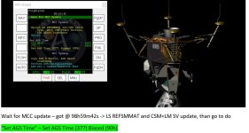
I am observing the following facts from approx. GET 82h to 98h…mission time.
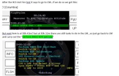
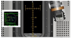
1) During “LM Comm activation” I saw a lot of yellow text concerning “voice checks”, see “photo 1 – voice checks”…can I skip all or shall I have to call up MCC menu and hit “1 – Voice check” any time a yellow text is displayed?
2) From about GET 83h to 84h while in the CSM, CSM tunnel hatch as well as LM hatch open, and CDR+LMP inside the LM I keep having “HI O2 FLOW” alarms from time to time, it happened at least 3 times every approx. 10min…the O2 flow meter start increasing go to max triggering the alarm, and then by itself is going down and then up again .. it seems like is having some sort of oscillatory behaviors…is it normal at this stage of the mission? If so, what is the physics behind this “periodical” behavior? I set the PAMFD ECS crew numbers as in the checklist, 2 in LM and 1 in CSM, and "in cabin" at all times ...
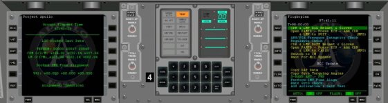
3) I saw the following yellow texts in the checklists at about 96h GET before the EPS LM activation: “LMP LM Familiarization”, “CDR Don PGA w/o Helmet&Gloves”, I guess I must do anything … right?
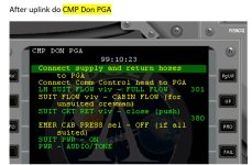
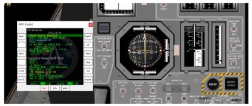
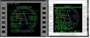
4) At time 96h20m during “CDR to LM ECS” there is a yellow text indicating “Connect CDR suit hoses”…I guess nothing to do here, just “skip” this line with PRO and go on with the next items in the checklist, right? (see photo 3) – same applies for the “Connect LMP suit hoses” later on the checklist for “LMP to LM ECS”….right?
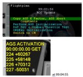
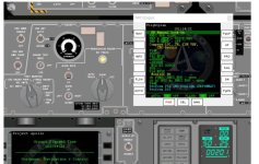
5) When time came to power up the C/W and LGC I got these orange alarms lights on I the LGC: TEMP, PROG, RESTART; while the last 2 went away later on (on schedule) the TEMP alarm was always steady on, even at about GET +97h after completing all LM systems tasks…is it normal? see “photo 4 – TEMP alarm still ON” on LGC.
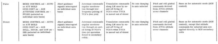
6) At about 97h during “Sec S-BD TR & PWR AMPL check” the following yellow texts are there: “Notify MSFN or SEC S-BD check” and “Perform Comm Check”…and again yellow texts at GET > 97h during VHF B and A checkout, “Perform Voice check on WHF Simplex B” and “Perform Voice Check on VHF Simplex A” --- I guess can be “skipped”…they are just for information, right? Same as my question 1?
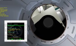
7) Finally a possible texture related issues? With the CSM tunnel hatch open and LM overhead hatch open from the CSM “looking trough the LM tunnel” you see the “outside of the LM” not the interior, from the LM “locking trough the CSM tunnel” you see the inside of the LEB, which seems ok. Can it be only a my PC issues? (I guess as I saw nobody reported this in the forum), see “photo
thanks.
PC
Sorry to be back so soon with CSM/LM related questions while in lunar orbit …but want to make sure I am OK with my missions and I didn't screw up things....
I am observing the following facts from approx. GET 82h to 98h…mission time.
1) During “LM Comm activation” I saw a lot of yellow text concerning “voice checks”, see “photo 1 – voice checks”…can I skip all or shall I have to call up MCC menu and hit “1 – Voice check” any time a yellow text is displayed?
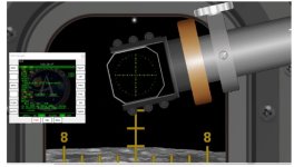
2) From about GET 83h to 84h while in the CSM, CSM tunnel hatch as well as LM hatch open, and CDR+LMP inside the LM I keep having “HI O2 FLOW” alarms from time to time, it happened at least 3 times every approx. 10min…the O2 flow meter start increasing go to max triggering the alarm, and then by itself is going down and then up again .. it seems like is having some sort of oscillatory behaviors…is it normal at this stage of the mission? If so, what is the physics behind this “periodical” behavior? I set the PAMFD ECS crew numbers as in the checklist, 2 in LM and 1 in CSM, and "in cabin" at all times ...
3) I saw the following yellow texts in the checklists at about 96h GET before the EPS LM activation: “LMP LM Familiarization”, “CDR Don PGA w/o Helmet&Gloves”, I guess I must do anything … right?
4) At time 96h20m during “CDR to LM ECS” there is a yellow text indicating “Connect CDR suit hoses”…I guess nothing to do here, just “skip” this line with PRO and go on with the next items in the checklist, right? (see photo 3) – same applies for the “Connect LMP suit hoses” later on the checklist for “LMP to LM ECS”….right?
5) When time came to power up the C/W and LGC I got these orange alarms lights on I the LGC: TEMP, PROG, RESTART; while the last 2 went away later on (on schedule) the TEMP alarm was always steady on, even at about GET +97h after completing all LM systems tasks…is it normal? see “photo 4 – TEMP alarm still ON” on LGC.
6) At about 97h during “Sec S-BD TR & PWR AMPL check” the following yellow texts are there: “Notify MSFN or SEC S-BD check” and “Perform Comm Check”…and again yellow texts at GET > 97h during VHF B and A checkout, “Perform Voice check on WHF Simplex B” and “Perform Voice Check on VHF Simplex A” --- I guess can be “skipped”…they are just for information, right? Same as my question 1?
7) Finally a possible texture related issues? With the CSM tunnel hatch open and LM overhead hatch open from the CSM “looking trough the LM tunnel” you see the “outside of the LM” not the interior, from the LM “locking trough the CSM tunnel” you see the inside of the LEB, which seems ok. Can it be only a my PC issues? (I guess as I saw nobody reported this in the forum), see “photo
thanks.
PC
Attachments
-
 LGC TEMP alarm on at all times is ok.JPG62.3 KB · Views: 485
 -
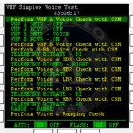 photo 1 - voice checks.JPG90.6 KB · Views: 539
 -
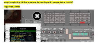 photo 2 - O2 flow hi alarm in CSM while 2 crew members are in the LM.JPG72.8 KB · Views: 444
 -
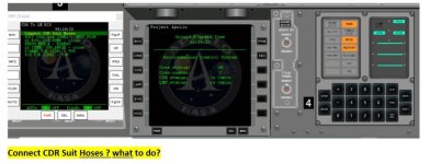 photo 3 - LGC power up and yellow message on cheklist.JPG70.4 KB · Views: 442
 -
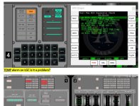 photo 4 -TEMP alarm still on at GET 97h.JPG88.5 KB · Views: 501
 -
 texture problems...why i see the LM throught the tunnel hatch.JPG70.9 KB · Views: 549
 -
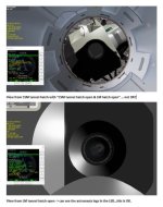 photo 5 - texture issues.JPG44.8 KB · Views: 508
") Feel free to keep using this one moving forward and we will see it just as easily.
Feel free to keep using this one moving forward and we will see it just as easily.

 -> AMAZING job you guys did here, I guess if some of you were working for NASA the next Moon landing would not be slipped away again...and again...I guess Artemis will be for my son to look, i lost any hope to can see human on the moon soon by my eyes.....
 very late for me now....