Project Air Breathing Turbojet Engine Model for Orbiter

Thunder Chicken

Fine Threads since 2008
Donator
Joined
Mar 22, 2008
Messages
4,327
Reaction score
3,248
Points
138
Location
Massachusetts
There was some discussion in the Orbiter Development forum about development of air-breathing engine models in addition to the scramjet for use within Orbiter in this thread:


To that end, I've been working to develop a performance model of a turbojet engine with afterburning capability that looks and behaves as a jet engine should. I've assembled a Python script that calculates the thrust for a given throttle position and ambient flight conditions.

Modeling Assumptions

This model implements a simplified ideal Brayton cycle engine analysis, which utilizes a cold air standard where the gas is assumed to be an ideal gas with constant specific heats, which simplifies the calculation but isn't strictly correct. In particular, the engine performance is very sensitive to the value of k (the specific heat ratio). The default value of 1.4 at 300 K tends to significantly overestimate overall engine performance.

Fuel properties are assumed to be something similar to jet A fuel, with lower heating value of about 42,800 kJ/kg and stochiometric fuel air ratio of 0.067. Fuel air ratios below this value are lean and combustion is complete; above this value they are rich and incomplete combustion and heat release is modeled.

In order to link the engine throttle to the engine thrust, the following assumptions were made:
  1. The steady engine shaft speed is linear with throttle position (approximately true based on published performance data)
  2. The air volume flow rate is proportional to engine shaft speed (based on turbomachinery scaling laws)
  3. The engine pressure ratio is proportional to shaft speed squared, and therefore to throttle position squared (again based on turbomachinery scaling laws)
These assumptions linearize the model so no iteration is needed, and so it should be a straightforward implementation, and I think they should lead to a physically realistic simulation.

Required Inputs

This model was created to strike a balance between detailed engine modeling and performance. It is meant to produce a suitable result when provided some basic engine performance parameters that may be easily found on the Internet for a given engine. Currently this is the minimum data that must be provided to implement a particular engine:

At full throttle at sea level:
  • Inlet diameter of engine [m]
  • Maximum thrust with afterburner (max_thrust_ab) and without afterburner (max_thrust) [kN]
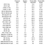
  • Maximum overall engine pressure ratio (rp_max) [-]
  • Air mass flow rate at full throttle (air_mass_flow_max) [kg/s]
  • Fuel flow rate at maximum thrust without afterburner (fuel_mass_flow_max) [kg/s]
  • Fuel flow rate at maximum thrust with afterburner (fuel_mass_flow_max_ab) [kg/s] if afterburning is implemented.
  • Bypass Ratio (bpr) [-]
  • Fan Pressure Ratio (fpr) [-]
What this engine model should do:
  • It should mimic the behavior of a real jet engine so far as thrust developed at a given throttle position and flight conditions.
  • At constant throttle setting, thrust will decrease with altitude due to reduction in air density. Flameout behavior can be implemented. A jet with this engine model should not be able to fly out of the atmosphere due to air starvation.
  • It should be able to determine realistic fuel consumption rates.
  • The absolute temperatures and pressures calculated in the engine should trend appropriately compared with a real jet engine.
What this engine model WON'T do:
  • It will not exactly model the temperatures, pressures, and thrust of a particular jet engine. It should look and act like a jet engine, and with some tweaking it can be made to approximate the thrust and fuel consumption of a particular engine, but that is where the similarity ends.
  • It will not model compressor stall or surge, or exact compressor or turbine behavior. To do this would require measured compressor and turbine performance maps which are generally proprietary and hard to get for particular engines.
  • It will not model turbine lag or any other transient. It is a 1-D quasi-equilibrium process model.
  • It currently cannot distinguish the amount of available oxygen in a given atmosphere. It simply assumes that the atmosphere is air as found on Earth, so this engine will "work" even on planets with sufficient atmospheric pressure. Modifications like inverted engines that can take a hydrocarbon atmosphere like on Titan and burn it using oxygen consumed as propellant are possible, as well as other combustion processes utilizing atmospheres other than air, but the gas properties and combustor processes will need to be modified accordingly.
Future plans

There are several camps about where this model should go: into Orbiter itself, as a code example for add-on developers, or maybe an API that will produce add-on engine code for input engine performance parameters. For the time being, I think the thing to do is to get this into an add-on in Orbiter, fly it, and see what needs to be modified and refined. @Urwumpe seemed willing to take my math model and try to implement it in an add-on that we can check out in Orbiter. Maybe we could make a T-38 trainer or something similar and see if these engines push it around like the real thing?

I hope this works out. It's not done yet, but I am hopeful something polished will come from this that will enable realistic atmospheric flight in Orbiter.

Cheers! :cheers:

UPDATE August 14, 2022: Jet Engine Library for Orbiter 2016 is now available through Orbiter Hangar!

UPDATE August 6, 2022: Jet Engine Library for Orbiter 2016 is now available for testing! Unzip the posted zip file to your add-on directory and read the Quick Start Guide for how to implement the engine.

UPDATE July 18, 2022: It works! Now to get it documented and the code bundled into some useful and accessible format for add-ons. Stay tuned.

UPDATE July 9, 2022: The model has been updated with an implementation allowing bypass turbofans as well as jet engines. The Python code uses modules containing the engine configuration data needed from literature sources.
 
Last edited:

Linguofreak

Well-known member
Joined
May 10, 2008
Messages
5,017
Reaction score
1,254
Points
188
Location
Dallas, TX
In order to link the engine throttle to the engine thrust, the following assumptions were made:
  1. The steady engine shaft speed is linear with throttle position (approximately true based on published performance data)

What exactly does "throttle" mean here? I know what it means for a reciprocating gasoline engine, but I'm less clear on what throttle lever position on a jet engine actually controls. Most of the reading I've done that's said anything about how pilot inputs are translated to engine parameters deals with modern engines with digital control: throttle lever position translates to a command to a microcontroller that knows the compressor and turbine maps and uses that information to interpolate (presumably linearly) between idle and maximum rated thrust for the ambient airstream conditions.

I'm less familiar with how the throttle actually controlled things on earlier jets with a mechanical linkage between the throttle lever and something in the engine assembly. Is it just a linear fuel flow rate thing? Is there some adjustment for static/dynamic pressure at the inlet? How easy will it be to get the model into states that would break an actual engine with similar parameters? If throttle is just fuel flow, I imagine that slamming in full throttle on the ground for an engine built for Mach 2 at 60,000 feet might cause issues.

It will not model turbine lag or any other transient. It is a 1-D quasi-equilibrium process model.

This is probably one of the more desirable items in the "model won't do this" list to implement: being able to hammer in the throttle and get instant full thrust from a jet will feel weird, and for many early jets hammering the throttle was a quick way to achieve flameouts or engine-rich-exhaust transients.

  • It currently cannot distinguish the amount of available oxygen in a given atmosphere. It simply assumes that the atmosphere is air as found on Earth, so this engine will "work" even on planets with sufficient atmospheric pressure. Modifications like inverted engines that can take a hydrocarbon atmosphere like on Titan and burn it using oxygen consumed as propellant are possible, as well as other combustion processes utilizing atmospheres other than air, but the gas properties and combustor processes will need to be modified accordingly.

It would perhaps be good to add some means of specifying atmospheric composition details in planetary config files to Orbiter.

Future plans

There are several camps about where this model should go: into Orbiter itself, as a code example for add-on developers, or maybe an API that will produce add-on engine code for input engine performance parameters. For the time being, I think the thing to do is to get this into an add-on in Orbiter, fly it, and see what needs to be modified and refined. @Urwumpe seemed willing to take my math model and try to implement it in an add-on that we can check out in Orbiter. Maybe we could make a T-38 trainer or something similar and see if these engines push it around like the real thing?

I'd vote for inclusion in Orbiter or as a co-distributed library.
 

Thunder Chicken

Fine Threads since 2008
Donator
Joined
Mar 22, 2008
Messages
4,327
Reaction score
3,248
Points
138
Location
Massachusetts
What exactly does "throttle" mean here? I know what it means for a reciprocating gasoline engine, but I'm less clear on what throttle lever position on a jet engine actually controls.
That's actually a good question and not something I had considered previously. In this code, it is assumed that some input throttle position is linear to the mass flow of fuel and volume flow of air. It is a quasi-steady model so the thrust is simply related to that throttle position through this model.

This input throttle position could be directly linked to the user throttle input through the Orbiter API, but it doesn't need to be. One could write a custom code that could lag the user throttle input from Orbiter to the effective input into this model. I'm afraid that's the only way any semblance of transients can be mimicked with this particular model. A fully-transient physics-based engine model that could do this would be more complicated than the Orbiter core.
 

DaveS

Addon Developer
Addon Developer
Donator
Beta Tester
Joined
Feb 4, 2008
Messages
9,429
Reaction score
680
Points
203
AFAIK, the throttle lever in a jet plane works like the Speedbrake/Throttle Control (SBTC) in the shuttle, in that it sets a commanded level, not the actual level. Jet engines need to spool up/down and that takes time, they can't go from one throttle position to another in an instant.

This has caused several catastrophic crashes in the past, where the flight crew realized that they need full power now but the engines couldn't deliver that and it has been found in the post-crash investigations by analyzing the FDR that the engines were commanded to go to full throttle but were in the process of spooling up at the time of impact.
 

Urwumpe

Not funny anymore
Addon Developer
Donator
Joined
Feb 6, 2008
Messages
37,588
Reaction score
2,312
Points
203
Location
Wolfsburg
Preferred Pronouns
Sire
This has caused several catastrophic crashes in the past, where the flight crew realized that they need full power now but the engines couldn't deliver that and it has been found in the post-crash investigations by analyzing the FDR that the engines were commanded to go to full throttle but were in the process of spooling up at the time of impact.

It used to be far worse at the times before hydraulic engine controllers came up. Many early german jet fighters simply crashed because the young unexperienced pilots rammed the throttle to the firewall during a dogfight, choking the engine in the process. Later, early hydraulics simply fixed that by making the amount of fuel metered into the engine depend on the pressure at the end of the compressor. And then came FADEC.

PS: I don't expect this model to be perfect. Its a first start and I am thankful to have expert aid there. If the resulting implementation is good enough to create the Hermes Carrier aircraft (modified A300), I am fine, really. We can get better and more detailled implementations later.
 

Thunder Chicken

Fine Threads since 2008
Donator
Joined
Mar 22, 2008
Messages
4,327
Reaction score
3,248
Points
138
Location
Massachusetts
PS: I don't expect this model to be perfect. Its a first start and I am thankful to have expert aid there. If the resulting implementation is good enough to create the Hermes Carrier aircraft (modified A300), I am fine, really. We can get better and more detailed implementations later.
As I mentioned, things like turbine lag and other transients, multiple spools, FADEC controlled throttle position, etc.. can be modeled upstream of this engine module. Some engines can throttle up quite quickly without choking, while others have so much rotating inertia that it can take some time to bring the power up. Some flame-out if you look at the throttle too quickly. Those sorts of behaviors would really need to be modeled separately, and would need to be specific to a particular aircraft. This engine model basically will deliver generic cruise performance at a particular throttle input and behave sensibly with altitude (I hope).

To truly model all the transients, multiple spools, etc.. in a physically realistic manner is challenging even for NASA and other commercial organizations. There are codes out there that can do this, but they aren't always numerically stable. They are also not computationally light, and they require performance maps for the compressor and turbine that either must come test stand measurements which are not really accessible to the average Orbiter user.

@Urwumpe - I trust that you can deal with the Python code as a starting point and translate it into C++ without too much difficulty. I tried my best to comment everything well so you can see what needs to be done. If you have any questions let me know.
 

Thunder Chicken

Fine Threads since 2008
Donator
Joined
Mar 22, 2008
Messages
4,327
Reaction score
3,248
Points
138
Location
Massachusetts
@Urwumpe - one thing also, I realized that since I linearized the mass flow calculations that I can use the full proper form of the thrust equation that accounts for the small reaction mass of the fuel injected in the combustor and afterburner.

The original thrust calculation (lines 185-187):
Python:
    # Calculate thrust

    thrust = m_air*(V7 - V0)    #engine thrust [N]

can be replaced with this:
Python:
    # Calculate thrust

    thrust = (m_air + m_fuel + m_ab)* V7 - m_air * V0    #engine thrust [N]

The difference should be practically negligible but every few % helps. I've updated as Revision 1 and attach the new code here.
 

Attachments

  • Turbojet_for_Orbiter_v1.zip
    2.8 KB · Views: 7

Thunder Chicken

Fine Threads since 2008
Donator
Joined
Mar 22, 2008
Messages
4,327
Reaction score
3,248
Points
138
Location
Massachusetts
I looked for a range of afterburning turbojet engines in the data source linked in my previous post and am plotting the model thrust results in comparison to the published thrust data for different values of the specific heat ratio k. The terminology dry means without afterburning and wet means with afterburning. It seems that the default k of 1.4 (cold air standard at 300K) actually does a reasonable job across the range of engines. It also seems that the afterburner model tends to slightly overestimate the thrust increase due to afterburning, which isn't surprising as I am assuming no frictional losses in the nozzle. Still, it's quite capable of getting within a few percent of the actual engine performance provided with nothing other than air, fuel, and thrust values at full throttle.

The Olympus 593 data is suspect - I think the indicated thrust is actually with afterburner based on the specific fuel consumption, and there is no other thrust data given so it's not possible to verify.


Thrust Model 1.2.png
Thrust Model 1.2 110kN.png
Thrust Model 1.4.png
Thrust Model 1.4 110 kN.png
 
Last edited:

Urwumpe

Not funny anymore
Addon Developer
Donator
Joined
Feb 6, 2008
Messages
37,588
Reaction score
2,312
Points
203
Location
Wolfsburg
Preferred Pronouns
Sire
That Olympus 593 data fits best to the early prototype version with reheat (136 kN). The final production version had 142 kN dry and 169 kN with reheat.
 

Thunder Chicken

Fine Threads since 2008
Donator
Joined
Mar 22, 2008
Messages
4,327
Reaction score
3,248
Points
138
Location
Massachusetts
That Olympus 593 data fits best to the early prototype version with reheat (136 kN). The final production version had 142 kN dry and 169 kN with reheat.
Yes. Later in that same document there are a couple more entries for the Olympus 593 where they give take-off thrust which look like production model values, but no other information is available. The data is very sparse and confused, and it doesn't match what is on the Wiki page.

Garbage In, Garbage Out.
 

Urwumpe

Not funny anymore
Addon Developer
Donator
Joined
Feb 6, 2008
Messages
37,588
Reaction score
2,312
Points
203
Location
Wolfsburg
Preferred Pronouns
Sire
AFAIR, the problem with supersonic engines like the Olympus is, that only a small part of their maximum thrust is actually generated by the engine itself, while most of the engine pressure ratio is produced by the inlet.
 

Thunder Chicken

Fine Threads since 2008
Donator
Joined
Mar 22, 2008
Messages
4,327
Reaction score
3,248
Points
138
Location
Massachusetts
AFAIR, the problem with supersonic engines like the Olympus is, that only a small part of their maximum thrust is actually generated by the engine itself, while most of the engine pressure ratio is produced by the inlet.
Yes, but the engine data is usually presented for sea level stationary operation unless indicated. If they did it at another condition they would need to provide the flight conditions related to it, otherwise it is quite unusable.
 

Thunder Chicken

Fine Threads since 2008
Donator
Joined
Mar 22, 2008
Messages
4,327
Reaction score
3,248
Points
138
Location
Massachusetts
There may be a turbofan modification coming in sooner rather than later. It will require the user to provide an additional separate fan pressure ratio (fpr) and bypass ratio (bpr) to the code. The implementation seems to slot in pretty nicely to the existing code, but I really want to mine that engine data and validate the results as much as I can.
 

Thunder Chicken

Fine Threads since 2008
Donator
Joined
Mar 22, 2008
Messages
4,327
Reaction score
3,248
Points
138
Location
Massachusetts
Bypass turbofans have been enabled!

Below are the engine models that I have produced with their compression and bypass ratios and a comparison of their thrust values from the model compared to the specified reference, both full thrust and with afterburning.

Generally the model seems very robust and can produce a pretty good first-swipe performance model of a particular engine without any tweaking. It does very well on larger engines with low or no bypass fan. Owing to the complete lack of any component efficiency losses, this model tends to overpredict thrust on older, smaller turbojets as smaller turbomachinery generally have lower component efficiencies due to the increased surface area to flow volume. The model also struggles with engines with high bypass ratios, mostly because the fan dominates the thrust in these engines and the engine performance is very sensitive to fan pressure ratio, which generally is somewhere above 1 and below 3, depending on the amount of bypass. The best "fix" might be simply to scale the full-thrust output until it matches the engine specification you desire. Specific fuel consumption is baked into the model so fuel consumption should be accurate.

I've pulled out the code defining the various engine parameters into modules that are essentially configuration files. As with anything in life, the results are only as good as the inputs. Here is an example of one with the information needed to build a particular engine. The thrust values are only for reference and are not used to calculate thrust in the model.

Code:
# Minimum engine parameters that must be provided for model at 100% throttle
# SNECMA-M53-P2 Turbofan

air_mass_flow_max = 92          #air mass flow rate at full throttle [kg/s]
max_thrust = 65.0               #maximum thrust without afterburner [kN]
rp_max = 9.8                    #pressure ratio at full throttle [-]
sfc = 32.4                      #specific fuel consumption at full throttle [g/kN s]
bpr = 0.36                      #Turbofan bypass ratio (mass flow through fan / mass flow through core) 0 for pure turbojets
fpr = 2.0                       #Turbofan pressure ratio

max_thrust_ab =  95             #maximum thrust with afterburner [kN]
sfc_ab =  53                    #specific fuel consumption with afterburner [g/kN s]


Data Plot.png

Turbojet Model Comparison.jpg
 

Attachments

  • Turbojet_for_Orbiter_v2.zip
    11.1 KB · Views: 4
  • Turbojet Model Comparison.jpg
    Turbojet Model Comparison.jpg
    71 KB · Views: 4
Last edited:

Thunder Chicken

Fine Threads since 2008
Donator
Joined
Mar 22, 2008
Messages
4,327
Reaction score
3,248
Points
138
Location
Massachusetts
I'm struggling to get an IDE on my old laptop.

Several have suggested making an MFD for this thrust model simply to test it under flight conditions in the DG. I have my code mostly converted into C++ syntax and have it commented with what I would need to see data-wise for testing. Anybody willing to take it and work it into a MFD for me?
 

Thunder Chicken

Fine Threads since 2008
Donator
Joined
Mar 22, 2008
Messages
4,327
Reaction score
3,248
Points
138
Location
Massachusetts
Big thanks to @hagiasophia420 for getting my engine model into an MFD for flight testing! :salute:

1657580072733.png

Right now it's just calculating the thrust from the model with a dummy throttle and afterburner engagement based on ambient flight conditions. I can set airspeed and altitude in the DG autopilot, set the dummy throttle and afterburner setting, and get the model results in the left MFD at a flight condition determined from Surface MFD. I can then check against my Python script.

Onwards and upwards! Thanks again hagiasophia420!
 

N_Molson

Addon Developer
Addon Developer
Donator
Joined
Mar 5, 2010
Messages
9,271
Reaction score
3,244
Points
203
Location
Toulouse
That's more than a good start, if you have the engine data mapping it in terms of thrust should be the easy part (y)
 

Thunder Chicken

Fine Threads since 2008
Donator
Joined
Mar 22, 2008
Messages
4,327
Reaction score
3,248
Points
138
Location
Massachusetts
@hagiasophia handed this code back to me and I hopefully can get it into VS 2017 today and compile it myself. If I can do that I might make a stab at a flight add-on. Oh boy, another pyramid to build! Thanks again for setting me up and lowering the barrier to getting back into C++ add-on building.

Some quick tests seem to show the model behaving appropriately at speed and altitude, but there is a slight bias between the MFD results and results from the Python script. This may be due to my using Surface MFD to get flight data like Mach number, OAT, static pressures instead of getting them from the API directly. I've notice in Orbiter that some things like flight velocity don't quite exactly agree between the HUD and surface MFD and even the autopilot. I also suspect that the variable typing may be somewhat sloppy in Python and there may be some integer that should be floats, etc..

Getting better every day. Progress!
 

Thunder Chicken

Fine Threads since 2008
Donator
Joined
Mar 22, 2008
Messages
4,327
Reaction score
3,248
Points
138
Location
Massachusetts
Surface MFD returns the accurate flight conditions, so that isn't the issue for the numerical discrepancy. It's small, but noticeable.
 
Top