SSU Development thread (4.0 to 5.0) [DEVELOPMENT HALTED DUE TIME REQUIREMENTS!]

Status
Not open for further replies.

Face

Well-known member
Orbiter Contributor
Addon Developer
Beta Tester
Joined
Mar 18, 2008
Messages
4,390
Reaction score
577
Points
153
Location
Vienna
PSA time: if anyone knows C#, your knowledge is welcome here. :hello: There is no need to know anything about the shuttle (or even Orbiter). It's just logic to load and write text files, show options in a window and make some calculations somewhere in there, and I can deal with that math, so there's no need to even know what 1+1 is. :lol:

What do you need?
 

GLS

Well-known member
Orbiter Contributor
Addon Developer
Joined
Mar 22, 2008
Messages
5,877
Reaction score
2,868
Points
188
Website
github.com

Those have the heights of the fwd and aft domes as part of the segments... if the center segments are the same length, and the aft field joint is in the same place (same ET attach segment that attaches to the same ET), then all the field joints are in the same location. :shrug:
That commonality will allow the small bit of code to set segment offsets per motor type to be removed. After I'm done with the first run thru the meshes to clean hidden triangles and some small corrections, I'll put the FWC joints in the right place, along with adding the smaller diameter ET attach segment. In the end, I'll fix the ET attach struts.

---------- Post added at 02:29 PM ---------- Previous post was at 02:17 PM ----------

What do you need?

Well, I made some structure in there already, but I'm not well versed in the data structure-to-screen links, especially when some checks need to be done (e.g., not allow some "illegal" combination of parameters). File IO is pretty far along, I think. Maybe some work is needed in the icons and such, but that is secondary.

The work flow for the user should be:
- create a new mission (which would display a default mission), or open an existing mission file and display that;
- allow that data to be changed (with some checks);
- save the mission file;
- create and save (no display, at least not in an editable way) a scenario from the mission parameters and some extra parameters (mission phase, date, other vessels in the scenario, etc). For now the easiest (and probably most needed) would be launch scenarios.

The mission parameters conversion to scenario SSU vessel blocks should be easy, as we can define a default state for most things, so it would be a question of using the appropriate default.

All the code is in the Orbitersdk\SSUWorkbench folder.
 

Face

Well-known member
Orbiter Contributor
Addon Developer
Beta Tester
Joined
Mar 18, 2008
Messages
4,390
Reaction score
577
Points
153
Location
Vienna
Well, I made some structure in there already, but I'm not well versed in the data structure-to-screen links, especially when some checks need to be done (e.g., not allow some "illegal" combination of parameters). File IO is pretty far along, I think. Maybe some work is needed in the icons and such, but that is secondary.

I see that there is WPF with data-binding mixed with code-behind on click-events. I take it that this is not an intentional architecture?

The work flow for the user should be:
- create a new mission (which would display a default mission), or open an existing mission file and display that;
- allow that data to be changed (with some checks);
- save the mission file;
- create and save (no display, at least not in an editable way) a scenario from the mission parameters and some extra parameters (mission phase, date, other vessels in the scenario, etc). For now the easiest (and probably most needed) would be launch scenarios.

So the idea is to have the user fill out the tab pages, then click the "Create Scenario" button in the "Start" ribbon, then get an Orbiter scenario file, right?

Is there a reason for the plain text config format instead of e.g. JSON? Seems like you guys wrote a dedicated parser for that...

What is missing, anyway? Looks like your described work-flow is working already. Bugfixing? Adding missing values?
 

GLS

Well-known member
Orbiter Contributor
Addon Developer
Joined
Mar 22, 2008
Messages
5,877
Reaction score
2,868
Points
188
Website
github.com
I see that there is WPF with data-binding mixed with code-behind on click-events. I take it that this is not an intentional architecture?
Probably it isn't...


So the idea is to have the user fill out the tab pages, then click the "Create Scenario" button in the "Start" ribbon, then get an Orbiter scenario file, right?
Pretty much.


Is there a reason for the plain text config format instead of e.g. JSON? Seems like you guys wrote a dedicated parser for that...
The mission file predates me.... for now it works so... :shrug:


What is missing, anyway? Looks like your described work-flow is working already. Bugfixing? Adding missing values?
Yes, from what I remember it outputs something, but it's still missing some "bone" and most of the "meat"... subsystem scenario blocks and update the pad vessel "flavors", jump to mind.
When loading an existing mission file, e.g. STS-3, we should output something close to the STS-3 launch scenario we currently have.
I don't remember what time-to-launch options we have to create a launch scenario, but T-9m and T-1m seem like good starting points.
So that would be a good starting point IMO, but the architecture must also eventually support the choosing of payloads (and their position), so parsing the available vessels will be required, along with some edit box for the user to manually set that non-SSU vessel specific parameters (e.g., satellite antenna closed, etc).
Much later, other scenario starting points (orbit, entry, landing) should also be supported.

There's a thread for the SSUWorkbench, with the last things I did in it, and some discussions on it.

---------- Post added at 04:23 PM ---------- Previous post was at 04:22 PM ----------

BTW: the mission file parameters are described in the pdf manual.
 

Face

Well-known member
Orbiter Contributor
Addon Developer
Beta Tester
Joined
Mar 18, 2008
Messages
4,390
Reaction score
577
Points
153
Location
Vienna
Yes, from what I remember it outputs something, but it's still missing some "bone" and most of the "meat"... subsystem scenario blocks and update the pad vessel "flavors", jump to mind.

So there is actually a bug, because those blocks and "flavors" are not in currently, although filled in via mission config?

When loading an existing mission file, e.g. STS-3, we should output something close to the STS-3 launch scenario we currently have.

In other words, STS-3 mission scenario output vs. STS-3 predefined scenario is a unit test.

I don't remember what time-to-launch options we have to create a launch scenario, but T-9m and T-1m seem like good starting points.

Would this be another parameter currently missing from the available controls/mission-parameters?

So that would be a good starting point IMO, but the architecture must also eventually support the choosing of payloads (and their position), so parsing the available vessels will be required, along with some edit box for the user to manually set that non-SSU vessel specific parameters (e.g., satellite antenna closed, etc).

Do you mean parsing SC3 or stock Orbiter configuration files, or is there an additional SSU-specific vessel-description format?

Much later, other scenario starting points (orbit, entry, landing) should also be supported.

Another additional parameter like the time-to-launch options?

---------- Post added at 18:20 ---------- Previous post was at 17:45 ----------

After some code reading, I think there is not much missing, actually. The overall work-flow is working, what is missing to pass the STS-3 test is:

  • some position values are zero
  • subsystems
  • SWT, SRB and Pallet vessels
  • MFDs
The overall code structure is decent (perhaps not perfect, but what is perfect, anyway?), so there is "only" a content problem, no system problem.
As such, the implementer should have knowledge of SSU, really. C# knowledge is less of a concern IMHO.


What confuses me a bit is the roadmap. It looked like a scenario manipulation tool in the thread at first, not like a scenario creation tool. Currently it is the later.
 

GLS

Well-known member
Orbiter Contributor
Addon Developer
Joined
Mar 22, 2008
Messages
5,877
Reaction score
2,868
Points
188
Website
github.com
So there is actually a bug, because those blocks and "flavors" are not in currently, although filled in via mission config?
Yeah... the pad vessels got changed but I never got to work with that so it was never updated. Also, not all mission file parameters are defined in the pdf manual, but only those used by the vessels.
Looking at the pad parameters, we have LC-39A, B and SLC-6 to choose from. Maybe the best option is to add a "LaunchPadType" parameter, with the pad type/year... now a structured file makes sense :lol:


In other words, STS-3 mission scenario output vs. STS-3 predefined scenario is a unit test.
Maybe not that formal but yes, the output scenario should match the scenario we already have (not necessarily in vessel order, or specific subsystem values), i.e., it should be equivalent.


Would this be another parameter currently missing from the available controls/mission-parameters?
The scenario starting points would be a predefined list and it would be only an on-screen parameter option used for the generation of the scenario file. Each option might have it's own subset of options.


Do you mean parsing SC3 or stock Orbiter configuration files, or is there an additional SSU-specific vessel-description format?
Something like what the create vessel option of the ScenarioEditor does, show a list to the user. Then there should be an option to attach it to attachment xyz or put it in orbit (RPOS, etc, parameters via textbox input?), as well as the mentioned vessel specific parameter textbox.


Another additional parameter like the time-to-launch options?
Maybe grouping starting points into "launch", "orbit", "entry" is a good idea... maybe not. :idk:
In the end there should be several starting points: T-9m, T-1m, pre-OMS-2, EI-5m, TAEM, etc..., but for starters, just having 2 launch ones is a huge step forward.

---------- Post added at 05:42 PM ---------- Previous post was at 05:37 PM ----------

After some code reading, I think there is not much missing, actually. The overall work-flow is working, what is missing to pass the STS-3 test is:

  • some position values are zero
  • subsystems
  • SWT, SRB and Pallet vessels
  • MFDs
The overall code structure is decent (perhaps not perfect, but what is perfect, anyway?), so there is "only" a content problem, no system problem.
As such, the implementer should have knowledge of SSU, really. C# knowledge is less of a concern IMHO.
Like I said, some parts are done, others aren't... :shifty:


What confuses me a bit is the roadmap. It looked like a scenario manipulation tool in the thread at first, not like a scenario creation tool. Currently it is the later.
There was some indecision at first about what it should do, and scenario editing was, and is, a bit over the top. Mission file editing is already complex enough, so there's that and then scenario generation at specific points.

---------- Post added 11-11-19 at 03:03 PM ---------- Previous post was 11-10-19 at 05:42 PM ----------

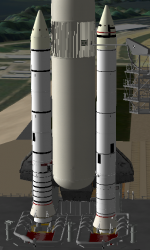
Initial cleanup work in the SRBs is done!
Next I'll have to correct some textures, as they were mapped backwards for some reason, and upon correction of that I noticed that the black triangles are wrong.
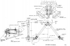
A few more "pieces of the puzzle" fell into place while I was going around the FWC meshes. First, the fwd dome joint area looked weird, and that is because the fwd segment was longer that it should be, so in barreled into the fwd skirt. Second, because the ET attachment segment has the diameter of the composite parts, instead of the actual metal parts, it "forces" the aft SRB/ET struts into a different place, so that's why things also don't fit in that area.
The FWC joints and diameters, plus the OFT textures, will be fixed in the next round thru those 30 meshes.
 

DaveS

Addon Developer
Addon Developer
Donator
Beta Tester
Joined
Feb 4, 2008
Messages
9,429
Reaction score
680
Points
203
CISS update: Things are progressing nicely. The main structure mesh is just about done, the propellant ducts as well. No need to work on the the helium bottles as they're simple spheres. The Deployment Adapter with its various hardware is about 75-80% done at this time. The main Adapter itself is completely done, it's just its attached avionics boxes that's left.
 

DaveS

Addon Developer
Addon Developer
Donator
Beta Tester
Joined
Feb 4, 2008
Messages
9,429
Reaction score
680
Points
203
Just to provide an update on where things stand on my end:

After wracking my brain for the past day-and-a-half over why the CISS and CUS would not mate properly, I've found that at least the Centaur G Prime is improperly sized. Using the station numbers and tank data given in the Centaur G Prime Technical Description document, I've found that just about everything is off in the length-axis. Here's a screenshot that shows it: https://www.dropbox.com/s/ep52xnbvn9d6it7/CentGPrime_size_inconsistency.jpg?dl=0

The red outline is our current Centaur G Prime while the solid object is a tank structural model made following the data in the Centaur G Prime Technical Description document. The black sections are the forward adapter and the aft adapter respectively. As you can tell from the screenshot, the engines are located way too far aft. I'm not sure how to proceed right now, if I should correct the size or keep it?
 

GLS

Well-known member
Orbiter Contributor
Addon Developer
Joined
Mar 22, 2008
Messages
5,877
Reaction score
2,868
Points
188
Website
github.com
Just to provide an update on where things stand on my end:

After wracking my brain for the past day-and-a-half over why the CISS and CUS would not mate properly, I've found that at least the Centaur G Prime is improperly sized. Using the station numbers and tank data given in the Centaur G Prime Technical Description document, I've found that just about everything is off in the length-axis. Here's a screenshot that shows it: https://www.dropbox.com/s/ep52xnbvn9d6it7/CentGPrime_size_inconsistency.jpg?dl=0

The red outline is our current Centaur G Prime while the solid object is a tank structural model made following the data in the Centaur G Prime Technical Description document. The black sections are the forward adapter and the aft adapter respectively. As you can tell from the screenshot, the engines are located way too far aft. I'm not sure how to proceed right now, if I should correct the size or keep it?

Do the engines collide with anything? (they would collide with a correct engine support structure, or whatever the CISS structure around them is called, but let's say that stays uncorrected)
I don't know if the CISS is in the correct place (I have no data on the location of the sill pins, but we should still target them to real positions), but IMO the most important detail is having a correct payload volume ahead of the Centaur (and IUS), so the stages must have their respective fwd ends at the correct place.
How much work are we talking here vs what is left to correct in the Orbiter? If it takes a day to shift the ends of the cones, cylinders and then the engines, maybe it's OK to take the delay. If we are talking of a week or so, then maybe the Orbiter is more critical as IMO that is the critical path to the release.
 

DaveS

Addon Developer
Addon Developer
Donator
Beta Tester
Joined
Feb 4, 2008
Messages
9,429
Reaction score
680
Points
203
The CISS's are at their correct locations. I'd estimate about day's worth of work on getting both Centaurs fixed up. Definitely not a week. Not sure how much work remains on the orbiter. I got the following on the list left, not sure how important they are.

- rad supply hoses not correct at front, and don't fit squares properly
- add faces to body flap attachment internal area
- add wing aft faces
- add bottom faces of seal panels

The technical description documents for both Centaurs are available here: https://www.dropbox.com/sh/cemn1sjdd6rw7s7/AAB6dnwxUZ3sUoCnFyJod1N4a?dl=0
 

GLS

Well-known member
Orbiter Contributor
Addon Developer
Joined
Mar 22, 2008
Messages
5,877
Reaction score
2,868
Points
188
Website
github.com
The CISS's are at their correct locations. I'd estimate about day's worth of work on getting both Centaurs fixed up. Definitely not a week. Not sure how much work remains on the orbiter. I got the following on the list left, not sure how important they are.

- rad supply hoses not correct at front, and don't fit squares properly
- add faces to body flap attachment internal area
- add wing aft faces
- add bottom faces of seal panels

The technical description documents for both Centaurs are available here: https://www.dropbox.com/sh/cemn1sjdd6rw7s7/AAB6dnwxUZ3sUoCnFyJod1N4a?dl=0

I haven't looked at the Orbiter recently, but (some of) the handrails were colliding with other parts, so they are not in the correct place. I think some of the sill structures are also not in the correct place. With the ExtAL pins now in the correct place, the PLBD drive collides with them, so they are also not in the right place.
If there is no position data for these items, then IMO we need to look at photos and use both the known positions of the pins of payloads and the PLB ring frames, to bound the positions of those items. That way, any future problems will be of a smaller magnitude.

One other thing I noticed while I was looking at the SRB corrections in the stack is gaps between the wing chines (the top of them) and the bottom part of the vehicle.

And only after all the parts are in the correct places, there is still the UV mapping to do. :facepalm:
 

DaveS

Addon Developer
Addon Developer
Donator
Beta Tester
Joined
Feb 4, 2008
Messages
9,429
Reaction score
680
Points
203
I haven't looked at the Orbiter recently, but (some of) the handrails were colliding with other parts, so they are not in the correct place. I think some of the sill structures are also not in the correct place. With the ExtAL pins now in the correct place, the PLBD drive collides with them, so they are also not in the right place.
If there is no position data for these items, then IMO we need to look at photos and use both the known positions of the pins of payloads and the PLB ring frames, to bound the positions of those items. That way, any future problems will be of a smaller magnitude.

One other thing I noticed while I was looking at the SRB corrections in the stack is gaps between the wing chines (the top of them) and the bottom part of the vehicle.
Dealt with these in the latest commit. Everything looks alright now.
 

GLS

Well-known member
Orbiter Contributor
Addon Developer
Joined
Mar 22, 2008
Messages
5,877
Reaction score
2,868
Points
188
Website
github.com
Corrected left SRB (still in "frankenstein version" with parts from several versions)
attachment.php

Don't pay attention to the segments on the right SRB colliding, that's because of the new mesh offsets.
The segment meshes now have their centers at some point of meaning, instead of being in "mid-air", so calculating the positions of things is much easier, although I don't think there will be any need to touch these things for quite a while. That said, things won't be perfect and the fwd skirt and frustum should have some work done in the future regarding the texture and mapping to remove the distortions associated with unrolling a cone into a flat surface, so the markings look well.
Also, had to rework the case texture to have the correct aspect ratio, so details aren't stretched or squeezed.
The relative position of all 5 segment meshes, plus the position of the SRB vessel (and meshes) in relation to the OV, were all done using the real numbers, and it all fits as it should. :hailprobe:
Only corrected the vertical placement of the aft SRB/ET attachments, and they don't match the ET... that's probably due to the ET not having being made to the "tanked" dimensions.
Still tons of work remaining, but tons of parts are unchanged between SRB versions, so part of it is just copy-paste. On the FWCs, only small gaps in knowledge remain, but nothing that would prevent a version in a few days.
 

Attachments

  • srbfrankenstein.PNG
    srbfrankenstein.PNG
    239.2 KB · Views: 340

GLS

Well-known member
Orbiter Contributor
Addon Developer
Joined
Mar 22, 2008
Messages
5,877
Reaction score
2,868
Points
188
Website
github.com
Just created the graphics branch, for future work in meshes and textures. This way any visual/performance/whatever issues are isolated, and we can always release a new version with the same graphics as the previous one.
Currently I dumped the half done SRB changes into it as a backup, and when I'm done it will be merged to the trunk. IMO work in the Orbiter.msh should remain in the trunk until it is in an acceptable for release, and then after that any changes should be made in the graphics branch.
 

GLS

Well-known member
Orbiter Contributor
Addon Developer
Joined
Mar 22, 2008
Messages
5,877
Reaction score
2,868
Points
188
Website
github.com
I just noticed that the texture SSUbay_norm.dds has 48MB!!!! :blink: Is it compressed at all? (can it be compressed?) That's not used by MOGE, but even D3D9 must be in pain with that one... :uhh:

A first, easy target for optimization, that can be released as SSU 5.1 is checking the compression level of all textures. For now, compressing that monster is a quick, easy and large gain.
 

GLS

Well-known member
Orbiter Contributor
Addon Developer
Joined
Mar 22, 2008
Messages
5,877
Reaction score
2,868
Points
188
Website
github.com
Finally got to the "target area" in the SRBs: the attachments, and they are now done! :hailprobe:
Now the LH2 end of the ET must be shrinked to "tanked dimensions", so it all fits as when the vehicle is in flight. The new struts are already in 2 parts, so that after the ET correction, the ET end of them will be put in the ET mesh.

So, remaining on the SRB side is the aft skirt (which is maybe 4cm too small in diameter at the aft end, and the top end might not be exactly correct), the HDPs are a tiny bit aft*, maybe add the cover to the cable tray in the ET attach ring area on the SPM/HPM and FWC, maybe make the RSRM joints a bit larger and then a final check of textures and materials before replicating the meshes for the right SRB.

*) probably will leave those 2 "as is" for now... the aft skirt doesn't really interface with anything, and the HDPs on the ground side are way off (MLP and SLC-6) and I can't do everything at once, so those will have to wait.

---------- Post added at 02:22 PM ---------- Previous post was at 01:18 AM ----------

Started looking at the ET with a ruler.... and I'm begining to wish I hadn't... :facepalm:
First the center of the mesh is "somewhere" in the LH2 tank, so if I want to know, e.g., where in the mesh is the Xt 2058 position, I can't really do math like "somewhere"-2058 = ??? The center of the feedlines at the umbilical plates is not correct... but there is the need to animate the Orbiter side of them. :shrug:
On the positive side, the relative positions of the OV/ET attachments seem OK, as does their position in relation to the OV.
 

DaveS

Addon Developer
Addon Developer
Donator
Beta Tester
Joined
Feb 4, 2008
Messages
9,429
Reaction score
680
Points
203
First the center of the mesh is "somewhere" in the LH2 tank, so if I want to know, e.g., where in the mesh is the Xt 2058 position, I can't really do math like "somewhere"-2058 = ???
I don't see how this is any different from the orbiter mesh. It is also located at a weird offset relative to where the 0 points are. The tip of the lightning spike is at Xt 327.207, if it helps. So the Xt 0 point is located 327.207 inches ahead of the lightning spike. Yt 0 is of course along the ET C/L while Zt 0 is located 234.5 inches below the ET C/L (ET C/L is at Zt 400).
 

GLS

Well-known member
Orbiter Contributor
Addon Developer
Joined
Mar 22, 2008
Messages
5,877
Reaction score
2,868
Points
188
Website
github.com
I don't see how this is any different from the orbiter mesh. It is also located at a weird offset relative to where the 0 points are. The tip of the lightning spike is at Xt 327.207, if it helps. So the Xt 0 point is located 327.207 inches ahead of the lightning spike. Yt 0 is of course along the ET C/L while Zt 0 is located 234.5 inches below the ET C/L (ET C/L is at Zt 400).

It's just not as linear as it could be. :shrug:
I just finished the shift and at first glance it looks good! Maybe the "tilted OV" noticed awhile back only happens with the empty ET. When the aft end of the ET comes up during tanking, it brings the OV up as well, and the fwd attachment then rotates up to accomodate the OV shifting, and that will make it "pitch down" towards the tank, so it should be all +/- lined up in-flight.
Anyway, at first the SRBs stopped matching the ET and the MLP, and it took me a while to realize that they are attached to the OV vessel, so they also need the "tank shrinkage shift" (but only in the attachments), so I'll just commit tomorrow as I'm tired right now.
 

DaveS

Addon Developer
Addon Developer
Donator
Beta Tester
Joined
Feb 4, 2008
Messages
9,429
Reaction score
680
Points
203
It's just not as linear as it could be. :shrug:
I just finished the shift and at first glance it looks good! Maybe the "tilted OV" noticed awhile back only happens with the empty ET. When the aft end of the ET comes up during tanking, it brings the OV up as well, and the fwd attachment then rotates up to accomodate the OV shifting, and that will make it "pitch down" towards the tank, so it should be all +/- lined up in-flight.
I've attached a schematic of the bipod struts from the SLWT SDH which shows a 5.5" offset between the tanked configuration and the unloaded configuration. The configuration we have now is for the unloaded configuration.
 

Attachments

  • ET_SDH_bipod.jpg
    ET_SDH_bipod.jpg
    200.5 KB · Views: 171
Status
Not open for further replies.
Top