Project VulcanCentaur

0324m.jpg

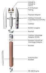
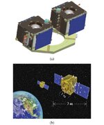
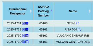
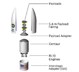
Attached is a scenario, with a simple EspaStar satellite, designated as NTS-3.
Scenario name is "VC4S USSF-106 to GEO.scn".
The VulcanCentaur addon needs to be installed before adding this scenario.

The satellite mass is 1489 kg dry + 310 kg fuel = ~1800 kg.
The launch azimuth in this scenario is 90°.

I usually wait half an orbit in parking (~400 km altitude), until crossing the equator northwards after the Philippines.
Then I burn to an ApA of 35600 km. This leads to reaching the Apogee over the Pacific Ocean close to the Americas.
Next is the circularization burn.
Final burn is due North, to minimize orbit inclination.
Attention: Switch in the Orbit-MFD the frame (FRM) to Equator (EQU) to control the inclination!
 

Attachments

Nicely done, flies better than my setup!
Only thing I do different is I burn 30 off prograde to zero inclination at start of circularizing burn while spacecraft is flying slower. Seems I use less fuel doing it then instead of after circularizing and get up spacecraft speed.
 
Only thing I do different is I burn 30 off prograde to zero inclination at start of circularizing burn
Yes, you are doing it the right way!
The circularization and inclination change burn are usually combined.

Problem is, Orbiters MFDs do not very well support this. You need to have one eye on the inclination value and one on the perapsis height.
When I tried this, I usually goofed it up.

Thats why I split it in two burns, where I have to watch only one parameter each.
Considering the lower speed at apogee, for a two-burn approach it might be more effective, to do the inclination change first (with a low dV), and then do the circularization burn. Will try that next time.
 
Stack1.jpg
I wonder how the stack inside the payload fairing may look like. :unsure:
Could it be like in the picture above?

Here each satellite is stacked on its own payload attachment fitting (PAF), which is connected to the satellite below, and finally to the Centaur stage. While this stack is pretty compact, it has the disadvantage of releasing the spent PAFs into the same orbit as the satellites. This would clutter the geostationary orbit with inert PAFs.

Or the PAFs stay attached to the GSSAP - satellites above, which would add dead mass to them.
 
Here's how they were configured for USSF-8, lot smaller than I thought they were.
 

Attachments

  • ussf8_expandedviewvehicle_externalwebsite-01.jpg
    ussf8_expandedviewvehicle_externalwebsite-01.jpg
    32.3 KB · Views: 4
  • GSSAP.jpg
    GSSAP.jpg
    50 KB · Views: 3
Last edited:
I'm betting the NTS-3/ESPA ring mounted to the cradle and just the GSSAP sat's were each released individually from the cradle.

I wonder if they didn't just mount onto the two sets of rails?
 

Attachments

  • NTS0324_image-1536x753 arrows.jpg
    NTS0324_image-1536x753 arrows.jpg
    59 KB · Views: 3
Last edited:
So it keeps getting more confusing, here is what Celestrak has put out. Johnathan has change the above link to just NTS-3 and USA-554.

Perhaps closer to the graphic by ULA with the two ESPA payload rings. Debris would be consistent with the adapter ring between them.
 

Attachments

  • Screenshot_2025-08-13_19-04-56.png
    Screenshot_2025-08-13_19-04-56.png
    19.1 KB · Views: 3
  • Screenshot 2025-08-14 at 08-21-44 Vulcan USSF-106.png
    Screenshot 2025-08-14 at 08-21-44 Vulcan USSF-106.png
    100.2 KB · Views: 3
Back
Top