Discussion Modeling Boats, Ships, and Other Watercraft in Orbiter? Experiments with Hydrostatics and the Touchdown Model

I'm moving my code over to my simple cube mesh for working on the hydrostatic pressure code. This cube has six mesh subgroups on each face with only four vertices and two triangles per group. Right now the code can only work with completely submerged triangles, so only the bottom two triangles have forces applied. All the side triangles should be partially submerged and so need special integration to determine the water level and pressure distribution and the location of the center of pressure.

Screenshot at 2024-11-22 15-45-00.png
 
OK, I have the box floating after a fashion. The density of the box is 75% that of water so the top floats 0.25 m above the surface, as expected. But it spins on its vertical axis crazily, stops, and then spins the other way. It's depth doesn't change, so I would expect the forces to be constant, so I am rather baffled at what is happening. I really wish I could see the force vectors to see if something is going wrong. It's really hard to diagnose problems with this code.

My Zorb with the same code does pretty well, until it tips over, where it just sinks. For some reason it seems that the mesh group on the upper half of the sphere isn't responding to the buoyancy calculation, so when the ball tips over, the amount of hull supporting the vessel effectively shrinks until it sinks. I'm wondering if a face of my box mesh might be dropping out in the same way.
 
Remember kids, vector subtraction is non-commutative. vec.sub(a,b) = a-b ≠ b-a, points from the tip of b to the tip of a, not from tip a to tip b.

I may have brain-farted and screwed that up the direction of operation a couple (dozen) times... That would make things spin for sure.

EDIT: It probably doesn't help that I am unsure when I need left-handed and right-handed operations.

Well, I needed to streamline my code anyway. All the hydrostatic integrations on the partially submerged surfaces involves integrating the volumes and centers of mass of irregular tetrahedra, so a helper function is in order.
 
Last edited:
OK, I think I have vanquished most of my sign errors. The box floats in a more or less stable fashion now, which is an achievement as there are only eight partially submerged triangles. I am integrating the hydrostatic forces and center of pressures of only the submerged portions of the triangles, so it's doing well. It spins crazily once it hits the water, but it stops. I think there is something going on in the rapid transients as the box enters the surface where the hydrostatic model forces calculated on such a granular mesh causes a large torque just as it enters the surface.

Screenshot at 2024-11-23 11-38-20.png

EDIT: I figured out why the box wouldn't stabilize. The drag on the box was acting at (0,0,0), which is the bottom center of the box. I moved the drag vector to act through the center of the box and it sits perfectly level and stable:

Screenshot at 2024-11-23 13-01-30.png
 
Last edited:
Applied the code to my Zorb...beautiful. With 50% of the density of water it floats within 3 mm of 0 altitude.

Screenshot at 2024-11-23 12-03-56.png

As with the box it seems to get a small unbalanced torque as it enters the water, but it stabilizes. The hydrostatic forces change rapidly on the triangles as they are submerged and I suspect there is some time resolution error that crops up that causes that, but once it is submerged it steadies out and behaves accordingly.

Setting the density to 99% of that of water, still just barely floats:

Screenshot at 2024-11-23 12-10-59.png

Tried for 99.9% of the density of water, but it sinks. I am calculating the vessel mass assuming a mathematical sphere, but the mesh is a tessellated polygon so the effective volume is slightly less than the equivalent mathematical sphere, so the effective density of the vessel will be slightly higher.

I think I'm ready to make a boat hull.
 
Last edited:
This would be really interesting to API-ify later. Conceivably, Orbiter could know where the water is and isn't with some kind of mask, or I guess it kind of already does?

Hypothetically we could also add bathymetric elevation too on earth, titan etc.

Ideas for Orbiter 2030....
 
This would be really interesting to API-ify later. Conceivably, Orbiter could know where the water is and isn't with some kind of mask, or I guess it kind of already does?
If you use vi:get_altitude(ALTMODE.MEANRADIUS), that gives the vertex depth relative to sea level. So in theory you could have something that has solid touchdown points on terrain above that altitude, but floats below that altitude. I am interested to see if I can get my Zorb to bounce down a mountain in Hawaii and then float in the sea. That could be a fun test. Lakes and other bodies of water at other elevations would need something more sophisticated.
Hypothetically we could also add bathymetric elevation too on earth, titan etc.
Yep. Subs could be a thing, though this model really shines for surface vessels. Completely submerged objects really don't need all the computational overhead of this model. You could just make a normal add-on with higher drag coefficients to account for the increased drag of water and apply a net constant buoyant force in the opposite direction of the weight vector at the center of pressure of the vessel.
Ideas for Orbiter 2030....
Boater 2030 :cool:
 
I tried this code on the Benchy mesh, insta-yeets to Alpha Centauri no matter what I do.

I suspect there is a Goldilocks zone of hull mesh resolution needed, and a challenging CFL stability issue. Hydrostatic forces can be extremely large. As a hull drops into the water, the applied force on the hull can change rapidly in a single timestep. In order to keep things sensibly resolved you want the velocity V, mesh triangle size dx, and timestep dt to play along like V dt/dx ~ 1 or less. For a velocity up to ~10 m/s, a time step of 0.01s, that implies a mesh size no smaller than about 0.1 m. That is about the resolution of the mesh on my Zorb, which suggests why it seems to behave reasonably well. But even that seems to have some spurious forces and torques when the steeply angled triangles on the bottom of the vessel hit the water quickly.

On the coarser end of the scale like with my floating box, with a mesh scale ~ 1m, there are massive forces being calculated on triangles opposing each other on opposite sides of the box. A small numerical imbalance between these forces can cause a large torque that causes the strange spinning behavior.
 
I went into my simple cube mesh and carefully examined the circumstances where the vessel seems to experience large and intermittent forces and torques. I thought it could have possibly been a mesh orientation or resolution issue, but it seems that the actual cause is a problem in my mesh file parser - for some reason it skips some vertices, which breaks the triangle connectivity tables, and actually produces some artificial triangles which interact with the hydrostatic pressure model in an unwholesome way. Quite definitely fixable, but it will require some code reorganization. The fundamental physics seems solid. Stay tuned.
 
OK, after much flailing and gnashing of teeth, and assistance from @Gondos, I figured out how to get the loaded mesh vertices and triangles in through Orbiter vs. parsing the mesh file directly. The user just needs to provide a list of the meshgroups that constitute the wetted hull parts that should participate in the force calculation. I also did a lot of simplification and code cleanup, and I can pretty much drop the Lua module into any config directory and get that mesh floating.

The spurious torque that I was experiencing is much improved. The issue I had with incorrect triangles being created that caused large torques was fixed by how I now load the vertices and triangles. But there is still some torque that happens when certain surfaces enter the water. It has something to do with the forces calculated for the special cases of the partially submerged triangles, but I am less certain that it is a bug now. I am somewhat suspicious that it may be an artifact of how my meshes are triangulated. The simple box that I use has six meshgroups, one for each side. There are four vertices and two triangles defining the square side with a diagonal. And the diagonal is canted at the same angle on each face. My sphere is triangulated in a similar way, like in this image:

image2017-6-16_19-3-54ecaa.png

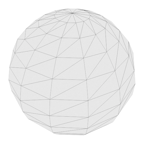
Imagine a globe where it is subdivided into rectangles of latitude and longitude, and triangles are created by cutting them at a diagonal. As with the box, all of the diagonals are canted in the the same way, and aren't normal to the center of the sphere. So if there was any imbalance in the forces calculated and their center of pressure, it would apply a torque, and all the triangles on the waterline would apply a similar torque in the same direction.

I'd be curious to try my Zorb model with a mesh with equilateral triangles where the normals all pass through the center of the sphere like this:

5.png

Something I could do would be to reverse the diagonals on opposite sides of my box and see if the spurious torques cancel. Off to the text editor and Orbiter...
 
Last edited:
It seems that the box mesh was already set up that, if level, forces on one side of the box would have exactly canceled those on the other. There shouldn't be a torque when the box is floating level. The spinning is chaotic, fast one way, stops, spins same way, reverses, etc.. It typically stabilizes, so I'm thinking again that it is some numerical issue when the box just hits the water.
 
So I made a little skiff mesh (by hand! I'm getting good at this).

Screenshot at 2024-11-27 20-35-42.png

I want to see how a real hull shape behaves with the model. It's a pretty coarse mesh, about 52 exterior hull triangles total.
 
So this is pretty much what happens when I drop the boat into the water, which might actually be correct:


It seems that the biggest hurdle with the hydrostatic model is getting these vessels into the water and surviving those initial transient forces without getting yeeted.

Honestly, I think the sanest way to mimic buoyancy in Orbiter is using the touchdown point model. It's stable, it's easy to implement from a coding standpoint and in computational effort, and it behaves more or less correctly. Here's dropping the skiff into the water and rocking the boat with a couple of add_force instances.

skiff_spring_model.gif

rockin_the_boat.gif
 
It seems that the biggest hurdle with the hydrostatic model is getting these vessels into the water and surviving those initial transient forces without getting yeeted.

Honestly, I think the sanest way to mimic buoyancy in Orbiter is using the touchdown point model. It's stable, it's easy to implement from a coding standpoint and in computational effort, and it behaves more or less correctly. Here's dropping the skiff into the water and rocking the boat with a couple of add_force instances.

View attachment 41308

View attachment 41309
LOVE IT TC !!
 
That's amazing. I'll make you a small boat when I'll have some spare time.
 
Does anyone see any problem with this rudder implementation? It should be delivering enough force to spin the boat in circles but doesn't seem to do anything. It's in clbk_setclasscaps():

Code:
vi:create_controlsurface(AIRCTRL.RUDDER, 1, 100, {x=0, y=0, z=-2.5}, AIRCTRL_AXIS.YPOS, 0.5)

get_adclevel(AIRCTRL.RUDDER) is reporting the correct rudder inputs, but I'm not able to turn the vessel.

There is no rudder to animate, I just want the force for the time being. I want to see if I can put a motor on it and putt it around a bit. A airfoil hydrofoil will need to be defined for the hull to lift it as it increases speed. I want to see if this produces something that behaves like a motorboat.

The hydrostatic force calculations may be for naught due to stability issues, but all of the code delineating the hull and getting the triangle areas and such makes it possible to determine the spring contact forces necessary to mimic buoyancy. I could potentially bundle it in a way where the user identifies the wetted hull surface meshgroups, and the code could pull the vertices and triangles, create touchdown points for all unique vertices, and set their stiffness and damping using an average area determined by adding up the hull areas and dividing by the number of touchdown points.
 
Last edited:
Cruising off coast at KSC:

crusing_off_ksc.gif

I put a horizontal airfoil in that lifts the hull out of the water as speed increases so it planes a bit. The surface clips through the hull of course, but a nice hull with a deck and some particle streams for a wake and this would look not bad.

I wrote a function that takes the hull meshgroup vertices, removes the redundant ones, and sets them to touchdown points with the proper buoyancy "stiffness". It mostly works, but it has a slight list which suggests that one or more vertices may still be duplicated. That makes those points extra buoyant. I have to chase down that issue, but once I close on that I'll bundle this up and put it out as an add-on.
 
Back
Top