You are using an out of date browser. It may not display this or other websites correctly.
You should upgrade or use an alternative browser.
You should upgrade or use an alternative browser.
Project Mir station complex / UR-500 family
- Thread starter MaxBuzz
- Start date
MaxBuzz
Well-known member
truss transitional (Переходный отсек) rocket proton consists of two parts truss (ферма) and spacer (проставка) it splits in half


I'm trying to figure out where the grate goes from the second stage

I'm trying to figure out where the grate goes from the second stage
Last edited:
MarkWatney2015
The Desktop Orbinaut
- Joined
- Oct 14, 2016
- Messages
- 1,274
- Reaction score
- 1,627
- Points
- 128
- Location
- San Jose Del Monte, Bulacan
- Preferred Pronouns
- He/him
I'm trying to figure out where the grate goes from the second stage
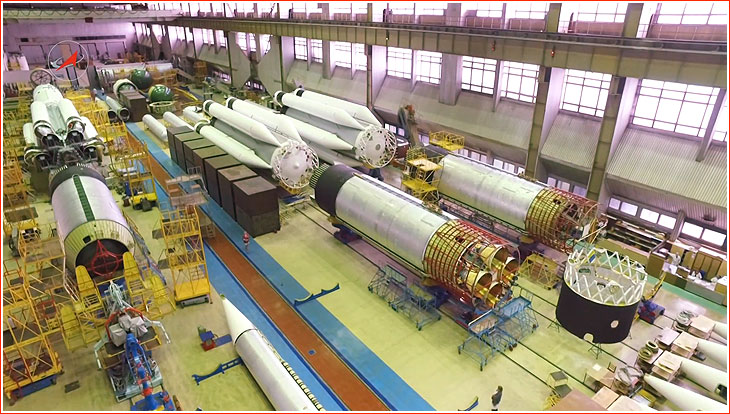
The interstage grate from the second stage is exposed in this photo during production (the red metal rods surrounding the four RD-0210 engines)

While I still have details to add (first stage aft bulkhead central "plate/connection"), interstage pipelines connections, stage 2 fore section and "Proton" satellite, this should give you a foretaste of the original test article (41-42 meters tall) :


The Proton satellite looks very much like a truncated third stage with solar panels and heavy electronics (12 tons !) for high-energy particles science, possibly some ballast to evaluate the launcher performance.
The Proton satellite looks very much like a truncated third stage with solar panels and heavy electronics (12 tons !) for high-energy particles science, possibly some ballast to evaluate the launcher performance.


I need a good picture of the stage 2 top inside, Thorton did that part in great detail and I can't copy him or simply guess.
This is the best I can find right now, but it won't be enough, the stage 2 top is hidden by the scaffolding and bad lighting :

This is the best I can find right now, but it won't be enough, the stage 2 top is hidden by the scaffolding and bad lighting :


Well what we see here is the stage 3 top, already assembled with stage 2. On the left pic you have a Briz space tug on the foreground, which is the 4th stage used for commercial satellites launches. We have to check but I don't think there was a 4th stage for the Mir modules.
The good news is that I found some good stuff on Anatoly Zak's website. Of course right now I'm on the test articles and there is no known detailed footage of their assembly (it probably was one of the most top-secret things of its era). Still, I now know roughly how stage 2 and 3 are/were assembled. After the 4 test-flights they extended the 2nd stage interstage, so that they had room to fit a third stage with a decent nozzle and this is pretty much how the Proton-K is born. The Proton-M features improved engines, up-to-date electronics and structural optimization, but is other than that very similar.
My test article is now 41.5 meters tall, and this is very close from what it should be (the most accurate reference I found is "more or less 41 meters"), so I think we're good. I don't think it has separation motors, the quality of the pictures is very poor but we would notice them ; also they were unnecessary to deploy the Proton satellites, springs were enough for that.
I'm processing the first stage for Orbiter exporting, lot of mesh cleaning to do and of course this is where I notice differences with reference pictures. But I'm understanding better how it works, and that helps a lot. Also unless we find conclusive evidence of the contrary, the first stage should be common to all the Proton versions (I'm pretty sure there were some small differences, but we don't have enough material to figure them out, and Thorton didn't either).
The 4th stage shouldn't be very hard to do because 1) I already have a Blok-D model from the Energia 5 project 2) ILS Proton user manual provides very nice blueprints of the Briz upper stage.

Excellent pic I did not have, thank you ! I now understand where the 4 "dents" are on the drawings.
Yes and mostly it is a very different launch profile : adding a 4th stage doesn't really improve the LEO payload capacity, but is essential for higher orbits that require a re-start, lunar or interplanetary transfers. The 7K-L1, Lunokhod or Venera probes used a Blok-D as 4th stage. Briz was added later as a cheaper alternative - but it also was a bit unreliable.
Yes and mostly it is a very different launch profile : adding a 4th stage doesn't really improve the LEO payload capacity, but is essential for higher orbits that require a re-start, lunar or interplanetary transfers. The 7K-L1, Lunokhod or Venera probes used a Blok-D as 4th stage. Briz was added later as a cheaper alternative - but it also was a bit unreliable.
Test Article #1 rollout at Baikonur (you have to imagine a bit the rollout part ?) :
I'd say "not bad", I was expecting much worse. As expected Jarmo's new shader does its magic. No textures.

And top view from Blender, pipes and wires connected :

I'd say "not bad", I was expecting much worse. As expected Jarmo's new shader does its magic. No textures.
And top view from Blender, pipes and wires connected :
Last edited:
Rocket standing on Pad 81/23 coordinates, 25 July 1965 :

And a CIA stolen picture (only thing missing is the gray cover around the interstage, could be added as a prelaunch thing) :

I'll go for the .dll modules and we'll have a a good starting point for the whole Proton family. Modifications for the later versions should be :
Proton-K
Proton-M
So still a lot of work ahead but I solved most coding issues I had working on the Long March 5 (no its not dead, but I can't duplicate myself !!!), and I now have a working and accurate TVC code. So I'm rather optimistic at this point, Proton is much simpler because there are no independent boosters to manage. Each engine will have its own rotation matrix and that should do it.
And a CIA stolen picture
(only thing missing is the gray cover around the interstage, could be added as a prelaunch thing) :I'll go for the .dll modules and we'll have a a good starting point for the whole Proton family. Modifications for the later versions should be :
Proton-K
- Interstage : "modern" lattice XXX pattern instead of VVV
- Stage 2 : extended interstage, "dents" and other features shown on pictures posted above, and the set of separation motors
- Stage 3 : replacement of the test articles "Proton Satellite" by a real rocket stage (1 main engine + 2 verniers)
- Stage 4 : addition of the Blok-D to the stack
- Fairings : a variety of fairings to match the Mir station modules and other payloads (including, of course, fairings for Russian ISS modules).
- "Proton" and "CCCP" decals
Proton-M
- Enhanced engines characteristics and stages mass
- Stage 4 : addition of the Briz, Briz-M, Blok DM family, KVTK (fictional but planned).
- ILS standard fairings and various decals for commercial or international launches (ESA, NASA...).
So still a lot of work ahead but I solved most coding issues I had working on the Long March 5 (no its not dead, but I can't duplicate myself !!!), and I now have a working and accurate TVC code. So I'm rather optimistic at this point, Proton is much simpler because there are no independent boosters to manage. Each engine will have its own rotation matrix and that should do it.
Last edited:
Interesting quote from Anatoly Zak's website :
So they uprated the Proton for the heaviest Mir module.
In 1986, specifically for the launch of core module of the Mir space station, the thrust of RD-253 engine was increased by seven percent. It was achived thanks to a minor modification to the propellant flow control valves. Since then, engines incorporating this change have undergone extensive additional qualification firings, in order to approve them for use in standard production vehicles.
So they uprated the Proton for the heaviest Mir module.

Also if you have information on the engines thrust vector control system, that would improve realism. I'm going to find a solution that works, but might not match the reality. First stage RD-253 engines gimbal on 1 axis only.
MaxBuzz
Well-known member
first stage (six motors) can be deflected by 7 degrees 30 minutes
second stage (four motors) can be deflected by 3 degrees 15 minutes
(whatever it means)
The propulsion system of the first stage consists of six autonomous cruise Each rocket engine is installed on two traverses of the tail section of the side block. To control the thrust vector, the engine can be deflected by an angle of up to 7 degrees for 30 minutes using a hydraulic drive. For this, it is fixed in the bearings of the crossheads with the help of special trunnions in the area of the critical section of the chamber.
original text
Last edited:
first stage (six motors) can be deflected by 7 degrees 30 minutes
That means +-7.5°, and is consistent with the data I found;
second stage (four motors) can be deflected by 3 degrees 15 minutes
That means +-3.25°, I had not that one, thanks !
What I'd like to know is the axis on which each engine gimbals.
Also Google Translation Russian->French does a reasonable job, so I was able to get some useful information. Not what I was searching for, but everything helps.
Last edited:
Similar threads
- Replies
- 12
- Views
- 16K