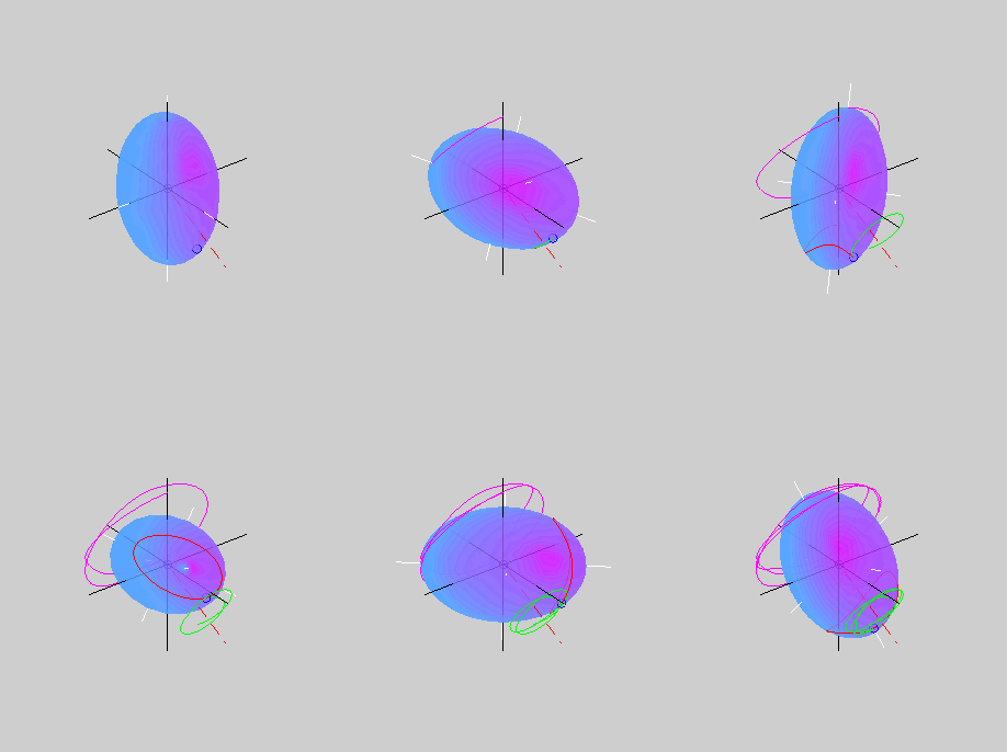
Attitude control for spin-stabilized satellites?

BrianJ

Addon Developer
Addon Developer
Joined
Apr 19, 2008
Messages
1,678
Reaction score
902
Points
128
Location
Code 347
Hi,
I'm just wondering how attitude control for spin-stabilized satellites is achieved.

Obviously, a "spin-stabilized" vessel is spun to maintain a constant spin-axis, but from time to time the spin-axis itself must need to be adjusted.

It would be very inefficient to de-spin the vessel, adjust the attitude, then re-spin.

So, I guess, the vessel is kept spinning and a nutation induced that will result in the spin axis being pointed in the correct direction. The nutation is stopped when the spin axis is pointed correctly.

But (and here's the $64,000 question) how to calculate the required nutation and the required torque to start and stop it???? (gyroscope physics? ugh!)

And is this really how attitude control is done for spin-stabilized satellites?

Anyone know anything about this subject?

Many thanks,
Brian
 

Urwumpe

Not funny anymore
Addon Developer
Donator
Joined
Feb 6, 2008
Messages
37,615
Reaction score
2,335
Points
203
Location
Wolfsburg
Preferred Pronouns
Sire
Actually, it is very simple if you have the satellite designed right by mass distribution:

Each nutation makes the axis of the satellite move around the surface of a cone. Now you initiate a nutation by a single RCS thruster ("tilting the axis") and stop it right after moving a half-cone. Your rotation axis now rotated by the opening angle of the nutation cone. Now you repeat the motion. Start nutation, stop nutation, start nutation, etc... until you have oriented your rotation axis at your desired target. For example have the satellite axis perpendicular to the LOS to the sun.

You don't need much complex calculations, since the width of the cone is just a simple relation between stored momentum in the satellite and the torque of the thruster. Your rotation rate is known, the direction in which you want to rotation your axis is also known. It is now all a matter of exact timing.

See here for a good intro:
http://www.aoe.vt.edu/~cdhall/courses/aoe4140/intro2adcs.pdf

The whole course can be found here:
http://www.aoe.vt.edu/~cdhall/courses/aoe4140/
 
Last edited:

BrianJ

Addon Developer
Addon Developer
Joined
Apr 19, 2008
Messages
1,678
Reaction score
902
Points
128
Location
Code 347
Thanks Urwumpe :) The ADCS course info in your links above is great! Let me read and digest that, and I'm sure I'll have more questions.

You don't need much complex calculations, since the width of the cone is just a simple relation between stored momentum in the satellite and the torque of the thruster.
Yes, that's the bit I need to figure out. :idk:

I've done an experiment with a DG in Orbiter - the situation doesn't seem that simple. If you start the DG rotating along it's Z axis and then apply a quick "pitch up" torque, the Z axis seems to follow a complex path across the sky - not a cone. But maybe that's an optical illusion (but I can always make an MFD to measure it ;-)

Interesting stuff - I shall enjoy reading the ADCS course material.

Cheers,
Brian
 

DaveS

Addon Developer
Addon Developer
Donator
Beta Tester
Joined
Feb 4, 2008
Messages
9,434
Reaction score
689
Points
203
BrianJ: I believe your problems relate to the fact that Orbiter 2006 doesn't model the physics of spin-stabilized spacecrafts very well, leading to the motions you observed. I believe this has been improved greatly in the next version.

In fact, there's a demo scenario of this which can be found in the Scenarios\2009 Edition\Demos\Spin stabilisation.
 

BrianJ

Addon Developer
Addon Developer
Joined
Apr 19, 2008
Messages
1,678
Reaction score
902
Points
128
Location
Code 347
Hi Dave,
the "Spin Stabilisation" scenario was included in the 2006 version I think, and I seem to remember some discussion about improved angular momentum handling at the time. Are there further refinements in the next version?

The strange behaviour of my "spin stabilized DG" experiment could also be due to a) The Z axis may not be the stable "major axis" b) finite RCS thruster time during "pitch up" while rotating c) other stuff I haven't thought of.

It's just that I finally got around to starting a "Giotto" probe add-on. Giotto was spin-stabilised at 15rpm but still had stringent pointing requirements during flyby of Halley (at 68km/s !). I could always take the easy way out and use animations to model the spin, but I wondered if it would be possible to actually make a realistic control system for it. We'll see.

Cheers,
Brian
 

tblaxland

O-F Administrator
Administrator
Addon Developer
Webmaster
Joined
Jan 1, 2008
Messages
7,320
Reaction score
25
Points
113
Location
Sydney, Australia
BrianJ: I believe your problems relate to the fact that Orbiter 2006 doesn't model the physics of spin-stabilized spacecrafts very well, leading to the motions you observed. I believe this has been improved greatly in the next version.
Orbiter 2006 integrates Eulers equations for rigid bodies just fine in my observation. Spin stabilisation is the same in Orbiter 20xx, it's just that the provided scenario file differs slightly. Brian's observation is actually to do with this:
Actually, it is very simple if you have the satellite designed right by mass distribution:
The DG does not have the appropriate mass distribution. It works best when you have two axes with low moments of inertia* and one axis with high moments of inertia. You get the best spin stabilisation when you rotate your vessel round the axis with the high moment of inertia.

EDIT: *These can be different if they are significantly less than the major principle axis. Having them different does complicate the guidance computations somewhat because the polhode motion is no longer a cone but something more complicated. The shape is not easily described (at least not by me :p) but it is something that can be visualised with Poinsot's ellisoid.
 
Last edited:

Urwumpe

Not funny anymore
Addon Developer
Donator
Joined
Feb 6, 2008
Messages
37,615
Reaction score
2,335
Points
203
Location
Wolfsburg
Preferred Pronouns
Sire
Actually, the spin model in 2006 is already good enough for most stuff, you just need the right spacecraft... I tested it with a Aries from World of 2001, you can directly after undocking from Station V use the RCS for slewing your rotation axis in the right direction and then do a separation burn.
 

BrianJ

Addon Developer
Addon Developer
Joined
Apr 19, 2008
Messages
1,678
Reaction score
902
Points
128
Location
Code 347
Just been doing some Orbiter experiments with a simple .cfg based vessel and varying the Inertia parameters. Setting the x & y parameters equal, and z > x, makes the Z axis precession quite clear and cone-shaped :)

You can point the vessel reasonably accurately just making the burns by eye.

Looks like I need to use angular momentum vectors to calculate the torque needed to give a specific precession angle, so I'm off for a cup of tea and a think about vectors.

Cheers,
Brian
 

BrianJ

Addon Developer
Addon Developer
Joined
Apr 19, 2008
Messages
1,678
Reaction score
902
Points
128
Location
Code 347
I've been doing some more experiments in Orbiter to try and get my head around how precession works - but I'm not seeing the behaviour I expect.
Probably because my understanding of angular momentum is wrong, but I'll get to that later.

First thing I noticed is that the behaviour at TimeWarp 1x is different to that at TimeWarp 10x, 100x or 1000x.

If anyone can be bothered, perhaps you can try the following experiment:

1. Make yourself a simple .cfg based spacecraft with inertia parameter Inertia = 1 1 2
I used the following .cfg
Code:
; === Config file for spintester  ===
ClassName = spintester
 
Size = 5.0
EnableFocus = TRUE
MeshName = ldef
Mass = 802
TouchdowPoints = 0 -2.93 9  -2 -2.93 -8   2 -2.93 -8
Inertia = 1 1 2
CrossSections = 4 4 4
PropellantResource1 = 150
ISP = 3000
MaxAttitudeThrust = 20
The ldef mesh is for visual ref, the Inertia values are chosen to make the maths easier when trying to do calulations.

2. Using the Scenario editor, put your vessel far out in space, away from any planetary gravity gradients, etc.

3. Set the x,y,z angular velocities to zero and set the orientation angles to zero(so you know where the z-axis was pointing when you start the rotation). Enable the Ecliptic Grid and Vessel Axes on the "Visual Helpers" tab(so you can see whats going on)

4. Now set the angular velocities to:
x = 0.8, y = 0, z = 90 (so your vessel is spinning rapidly around the z-axis and there is a very small pitch-up component)

Keep the TimeWarp at 1x - what do you see? I don't see any precession at all i.e. the z-axis rotates in one plane, describing a great-circle around the sky (or you could say it describes a cone with an opening angle of 180deg)

Now, press pause and set the TimeWarp to 10x.
Repeat steps 3 and 4.
At TimeWarp 10x (or 100x, 1000x), I see a clear precession effect with the z-axis describing a cone with opening angle of ~90deg.

(note: switch back to TimeWarp 1x while the precession is happening and it continues to precess)

I get this result consistently - anyone else get the same? It doesn't seem right to me - I would expect to see the precession effect at TimeWarp 1x as well as higher values (ignoring values > 1000x, I know the angular velocity propagation limiters kick in at high values)


OK, on to my next point - even when I do see the precession effect happening, it's not what I expect.

From what I've read, I thought that the precession axis is the Total Angular Momentum vector - is that right?

If yes - why can't I find the total angular momentum vector by summing the angular momentum vectors along the vessels x,y,z axes?

For instance in my experiment above, I thought the components of the total angular velocity vector would be:
x = PMI * mass * angular velocity = 1 * 952kg * (0.8 * PI/180)rad/s
y = PMI * mass * angular velocity = 1 * 952kg * 0 = 0
z = PMI * mass * angular velocity = 2 * 952kg * (90 * PI/180)rad/s

and the angle between this vector and the z-axis would be:
atan(x/z) = atan(0.8/180) = 0.254deg

But as you can see if you do the experiment above, the precession axis is ~45deg away from the z-axis.

Yech! I don't grok this at all! Can anyone confirm if Orbiter is handling angular momentum as it should? (and I'll go back to reading up on precession!)

Attached is a .pdf about the subject (can't remember where I found it, so I'll leave it here)

Thanks,
Brian
 

Attachments

  • Precession.pdf
    180.3 KB · Views: 13

JamesG

Orbinaut
Joined
Jul 9, 2008
Messages
511
Reaction score
0
Points
0
Location
Afghanistan? WTF!?!
Interesting read. I love to read mathematical proofs and "paper talk" descriptions of the common place.

Remember that gravity propigates even beyond its primary influence and orbiter keeps track of that even as subtle as it is. If you left your spacecraft spinning at 1x long enough it would probably build up a procession just like at time accelleration, unless this is a artifact of a programmatical rounding error.

I bet when you did your experiment you did not align the primary axis of rotation with the gravitational gradient (to or away from the sun). If you do, you will probably not find any or as much procession.
 

BrianJ

Addon Developer
Addon Developer
Joined
Apr 19, 2008
Messages
1,678
Reaction score
902
Points
128
Location
Code 347
Hi James,
thanks for the reply. However, I think the gravity gradient torque from the sun at 10AU out will be small. I get the same results if I disable "Gravity Gradient Torque" and "Non-Spherical Gravity" in the Orbiter Launchpad options, or even remove all planets from the solar system and set the mass of the Sun to 0.001 kg!

This is really about how "Torque Free Precession" works and how Orbiter handles it.

In a nutshell, two things have me puzzled:

1. Why do I get completely different behaviour in Orbiter when starting from the same initial conditions but using different TimeWarp settings i.e.
at Timewarp 1x = no precession (cone opening-angle 180)
at TimeWarp 10x to 1000x = precession (cone opening-angle ~90)

2. How can changing the total angular momentum by a very small amount give such a large deviation of the precession axis away from the vessel z-axis?

From my understanding, given the angular velocities and moments of inertia in my "experiment" I should get a precession around an axis at an angle of ~0.25deg to the vessel z-axis - but in Orbiter the angle is ~45.

Either my understanding is wrong (probable) or there's something not quite right with Orbiter's handling of angular velocities (possible).

At the end of the day, all I want to do is to be able to calculate the precession axis vector given the angular velocities around the vessel axes and moments of inertia of the vessel. Anyone can help with that?

OK, I'm going back to read those .pdf's on kinematics and precession again.

Thanks,
Brian

---------- Post added 02-14-10 at 12:32 AM ---------- Previous post was 02-13-10 at 01:49 PM ----------

OK, well, after much messing around with spinning spacecraft with different Inertia parameters, I have empirically arrived at the following formula for finding the angle between the precession axis and the spin axis (z-axis in my case)....in Orbiter, at least.

So for a vessel spinning rapidly around it's z-axis and given a small pitch-up rotation, the angle [math]\theta[/math] between the precession axis and spin axis is given by:
[math] \theta = atan[ (~I_x / ( (2I_x)-I_z)~)(\omega_x/\omega_z) ] [/math]
Where:
[math]I_x[/math] is the moment of Inertia around the x axis (or y axis, they must be equal)
[math]I_z[/math] is the moment of Inertia around the z axis
[math]\omega_x[/math] is the angular velocity around the x axis
[math]\omega_z[/math] is the angular velocity around the z axis (spin axis)

If [math]\theta[/math] is negative, the precession is in the opposite sense to the spin-axis rotation.

OK, you can see from the first term in the square brackets that when
[math]I_z = 2I_x[/math] the first term becomes undefined (or infinitely large, if you like) and strange behaviour results.

So by choosing my .cfg inertia parameter as Inertia = 1 1 2, I have immediately shot myself in the foot!

Indeed, as the value of [math]I_z[/math] approaches [math]2I_x[/math], the precession behaviour becomes stranger and stranger! (it seems to me)

And for values of [math]I_x < I_z < 2I_x[/math] the precession is in the wrong sense (as well as the precession axis being in a strange place!).

As usual, I'm willing to believe I've got everything backwards and upside down - but Orbiter's handling of precession effects doesn't seem right to me.

Cheers,
Brian
 
Last edited:

tblaxland

O-F Administrator
Administrator
Addon Developer
Webmaster
Joined
Jan 1, 2008
Messages
7,320
Reaction score
25
Points
113
Location
Sydney, Australia
I haven't had time to try your experiment in Orbiter, but your equation above does not look quite right to me. At the very least, in the case of a sphere, Ix=Iy=Iz and you would expect no precession to occur. Precession is predicted by your equation.
 

JamesG

Orbinaut
Joined
Jul 9, 2008
Messages
511
Reaction score
0
Points
0
Location
Afghanistan? WTF!?!
I think his equation presumes that there will be/is some procession (Iz). Also, procession really isn't motion on the Z axis. I mean it is, especally programatically in a simulator like Oribiter. But physically it is rotation around a secondary Y axis induced by input (mass redistribution, asymetric gravity gradients, you fingers bumping the top as you let it go, etc).
 

tblaxland

O-F Administrator
Administrator
Addon Developer
Webmaster
Joined
Jan 1, 2008
Messages
7,320
Reaction score
25
Points
113
Location
Sydney, Australia
But physically it is rotation around a secondary Y axis induced by input (mass redistribution, asymetric gravity gradients, you fingers bumping the top as you let it go, etc).
Those are examples of torque induced precession, but torque free precession is a very real phenomenon.
 

BrianJ

Addon Developer
Addon Developer
Joined
Apr 19, 2008
Messages
1,678
Reaction score
902
Points
128
Location
Code 347
I haven't had time to try your experiment in Orbiter, but your equation above does not look quite right to me. At the very least, in the case of a sphere, Ix=Iy=Iz and you would expect no precession to occur. Precession is predicted by your equation.

It doesn't look at all correct to me either - but it does describe the behaviour of torque free precession of vessels in Orbiter.

I would be interested to see if anyone gets the same results. I've tried for many different rotation and inertia settings and the equation predicts what will happen.

Particularly, you can look at the cases where Iz = 2Ix (precession axis is always at 90deg to the spin axis - except at higher time accel!)

Or where Ix < Iz < 2Ix
e.g. Inertia = 1 1 1.5
That's still an "Oblate Spinner" but the precession rotation is in the wrong sense - like a "Prolate Spinner"

I increasingly suspect a bug. Would be good if someone can look at this.

Thanks,
Brian
 
Last edited:

Andy44

owner: Oil Creek Astronautix
Addon Developer
Joined
Nov 22, 2007
Messages
7,620
Reaction score
7
Points
113
Location
In the Mid-Atlantic states
Those are examples of torque induced precession, but torque free precession is a very real phenomenon.

I seem to recall from a textbook that precession is defined as a change in the angular momentum, which is conserved, and thus requires an external torque, be it solar pressure, drag, gravity gradient, magnetic interaction, or thrust.

Are you confusing it with nutation?
 

tblaxland

O-F Administrator
Administrator
Addon Developer
Webmaster
Joined
Jan 1, 2008
Messages
7,320
Reaction score
25
Points
113
Location
Sydney, Australia
Are you confusing it with nutation?
Definitely not. Here is a good animation of a homogeneous ellipsoid rotating freely:
minor.gif

The text that goes with it makes interesting reading: http://www.aero.iitb.ac.in/~bhat/asymmetric.html

Brian: I threw your config file in to Orbiter quickly last night and seemed to get unexpected results in Orbiter 2006 P1 (time acceleration didn't make any difference though, ie, 1x and 10x yielded a cone with an aperture of 180°). I tried in the latest Orbiter RC and seemed to get different results but I didn't have enough time to see if they were close to expected or not. I'll report back when I get more time.
 

Andy44

owner: Oil Creek Astronautix
Addon Developer
Joined
Nov 22, 2007
Messages
7,620
Reaction score
7
Points
113
Location
In the Mid-Atlantic states
What the guy on that page is calling precession is not what I call precession, since in your diagram the angular momentum vector remains constant.

---------- Post added at 08:50 PM ---------- Previous post was at 08:44 PM ----------

According to wiki, there are two types of precession, torque-free and torque-induced... http://en.wikipedia.org/wiki/Precession

One of the texts I read said that the terms precession, nutation, and wobble are ill-defined and the meaning changes in other texts. That must be my problem here.
 

tblaxland

O-F Administrator
Administrator
Addon Developer
Webmaster
Joined
Jan 1, 2008
Messages
7,320
Reaction score
25
Points
113
Location
Sydney, Australia
One of the texts I read said that the terms precession, nutation, and wobble are ill-defined and the meaning changes in other texts. That must be my problem here.
I have found that in my experience too. For example, in a classical mechanics text on torque-free precession, the polhode motion shown in that animation above would be considered only precession with no nutation. Any nutation would be considered to be the variation of the polhode motion from that of the inertia ellipsoid's rigid body dynamics, be it from non-rigid effects or some torque-induced effects. Yet I've found in discussions of planetary axis precession that they consider nutation to be the variation from the polhode motion of a symmetric top, ie, a pure rigid body can still exhibit nutation if it is non-symmetric. I can see the validity of the argument both ways, but the terminology can be misleading.
 

tblaxland

O-F Administrator
Administrator
Addon Developer
Webmaster
Joined
Jan 1, 2008
Messages
7,320
Reaction score
25
Points
113
Location
Sydney, Australia
Brian: I ran tests on a different machine using your config file and an initial angular velocity vector of {2,0,20} deg/s. I observed the expected symmetric top type precession in both 2006 P1 and Beta 091124 (as best as I can tell. Cool idea for a module: add an angular velocity vector and angular momentum vector to the visual representation of the vehicle). If I can get fraps working here I will provide a video. I can confirm that I was definitely not getting this behaviour on my other machine last night. Weird...

EDIT: Have a look at this video and see if it looks anything like what you are getting and/or are expecting: http://orbiter-forum.com/images/orbiter_sym_top_precession.wmv (my apologies for the terrible frame rate, I am not having much luck with fraps atm, it used to be much better than this...)
 
Top